Dodge Durango (DN). Manual - part 38


  Index      Dodge     Dodge Durango (DN) - service repair manual 2000 year


Search            


Content   ..  36  37  38  39   ..


Dodge Durango (DN). Manual - part 38


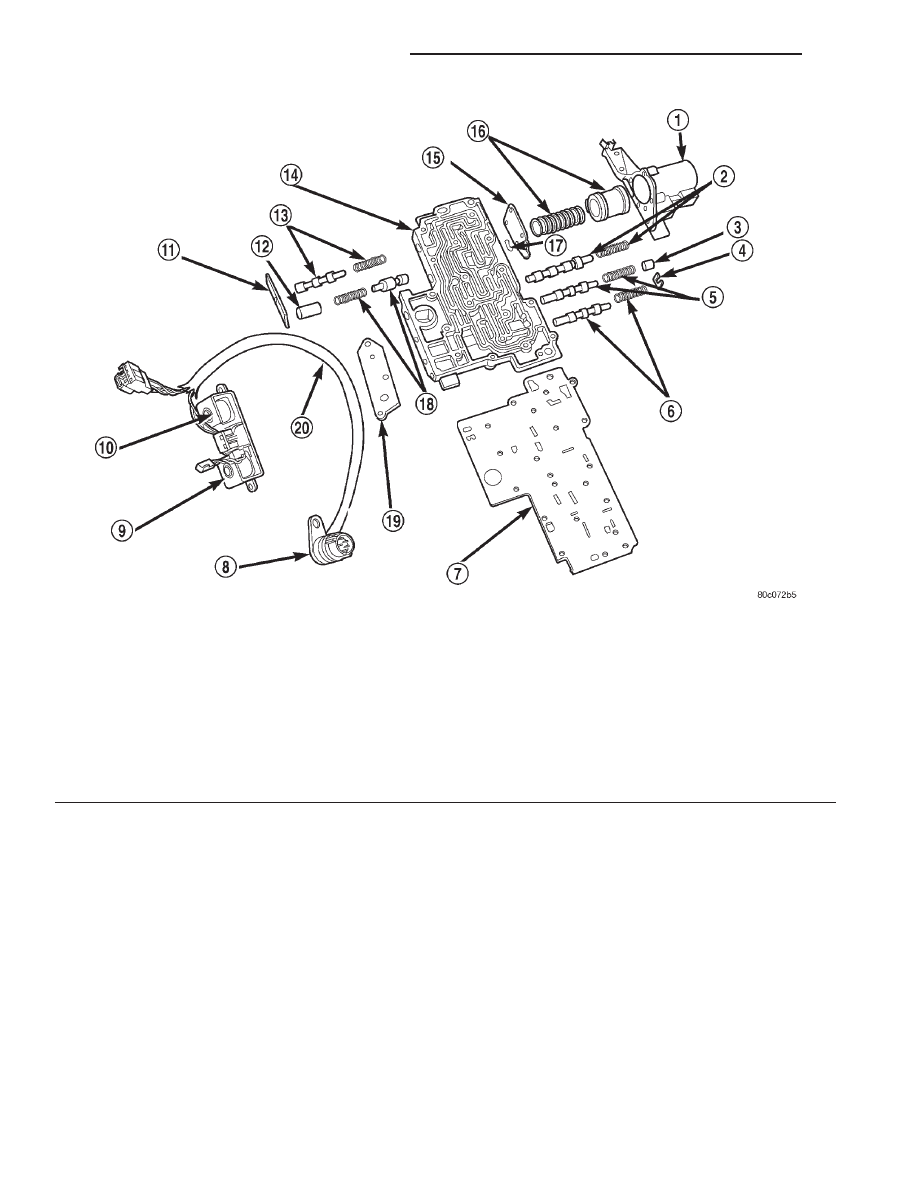
Fig. 21 Lower Housing Shift Valves and Springs

1 – 3-4 ACCUMULATOR HOUSING
2 – 3-4 SHIFT VALVE AND SPRING
3 – PLUG
4 – SPRING RETAINER
5 – CONVERTER CLUTCH VALVE AND SPRING
6 – CONVERTER CLUTCH TIMING VALVE AND SPRING
7 – OVERDRIVE SEPARATOR PLATE
8 – CASE CONNECTOR
9 – CONVERTER CLUTCH SOLENOID
10 – OVERDRIVE SOLENOID

11 – TIMING VALVE COVER
12 – PLUG
13 – 3-4 TIMING VALVE AND SPRING
14 – LOWER HOUSING
15 – ACCUMULATOR END PLATE
16 – 3-4 ACCUMULATOR PISTON AND SPRING
17 – E-CLIP
18 – 3-4 QUICK FILL SPRING AND VALVE
19 – SOLENOID GASKET
20 – HARNESS

21 - 18

42/44RE AUTOMATIC TRANSMISSION

DN

DESCRIPTION AND OPERATION (Continued)

OPERATION

NOTE: Refer to the Hydraulic Schematics for a
visual aid in determining valve location, operation
and design.

REGULATOR VALVE

The pressure regulator valve is needed to control

the hydraulic pressure within the system and reduce
the amount of heat produced in the fluid. The pres-
sure regulator valve is located in the valve body near
the manual valve. The pressure regulator valve train
controls the maximum pressure in the lines by
metering the dumping of fluid back into the sump.
Regulated pressure is referred to as “line pressure.”

The regulator valve (Fig. 22) has a spring on one

end that pushes the valve to the left. This closes a
dump (vent) that is used to lower pressure. The clos-
ing of the dump will cause the oil pressure to
increase. Oil pressure on the opposite end of the
valve pushes the valve to the right, opening the
dump and lowering oil pressure. The result is spring
pressure working against oil pressure to maintain
the oil at specific pressures. With the engine run-
ning, fluid flows from the pump to the pressure reg-
ulator valve, manual valve, and the interconnected

circuits. As fluid is sent through passages to the reg-
ulator valve, the pressure pushes the valve to the
right against the large spring. It is also sent to the
reaction areas on the left side of the throttle pressure
plug and the line pressure plug. With the gear selec-
tor in the park position, fluid recirculates through
the regulator and manual valves back to the sump.

Meanwhile, the torque converter is filled slowly. In

all other gear positions (Fig. 23), fluid flows between
two right side lands to the switch valve and torque
converter. At low pump speeds, the flow is controlled
by the pressure valve groove to reduce pressure to
the torque converter. After the torque converter and
switch valve fill with fluid, the switch valve becomes
the controlling metering device for torque converter
pressure. The regulator valve then begins to control
the line pressure for the other transmission circuits.
The balance of the fluid pressure pushing the valve
to the right and the spring pressure pushing to the
left determines the size of the metering passage at
land #2 (land #1 being at the far right of the valve in
the diagram). As fluid leaks past the land, it moves
into a groove connected to the filter or sump. As the
land meters the fluid to the sump, it causes the pres-
sure to reduce and the spring decreases the size of
the metering passage. When the size of the metering
passage is reduced, the pressure rises again and the

Fig. 22 Regulator Valve in Park Position

DN

42/44RE AUTOMATIC TRANSMISSION

21 - 19

DESCRIPTION AND OPERATION (Continued)

size of the land is increased again. Pressure is regu-
lated by this constant balance of hydraulic and
spring pressure.

The metering at land #2 establishes the line pres-

sure throughout the transmission. It is varied accord-
ing to changes in throttle position, engine speed, and
transmission condition within a range of 57–94 psi
(except in reverse) (Fig. 24). The regulated line pres-
sure in reverse (Fig. 25) is held at much higher pres-

sures than in the other gear positions: 145–280 psi.
The higher pressure for reverse is achieved by the
manual valve blocking the supply of line pressure to
the reaction area left of land #4. With this pressure
blocked, there is less area for pressure to act on to
balance the force of the spring on the right. This
allows line pressure to push the valve train to the
right, reducing the amount of fluid returned to the
pump’s inlet, increasing line pressure.

Fig. 23 Regulator Valve in Neutral Position

21 - 20

42/44RE AUTOMATIC TRANSMISSION

DN

DESCRIPTION AND OPERATION (Continued)

Fig. 24 Regulator Valve in Drive Position

Fig. 25 Regulator Valve in Reverse Position

DN

42/44RE AUTOMATIC TRANSMISSION

21 - 21

DESCRIPTION AND OPERATION (Continued)


Content   ..  36  37  38  39   ..