Dodge Durango (DN). Manual - part 23


  Index      Dodge     Dodge Durango (DN) - service repair manual 2000 year


Search            


Content   ..  21  22  23  24   ..


Dodge Durango (DN). Manual - part 23


LOOSE STEERING AND VEHICLE LEAD

CONDITION

POSSIBLE CAUSE

CORRECTION

EXCESSIVE PLAY IN STEERING
WHEEL

1. Worn or loose suspension or
steering components.

1. Inspect and repair as necessary.

2. Worn or loose wheel bearings.

2. Inspect and repair or adjust
bearings.

3. Steering gear mounting.

3. Tighten gear mounting bolts to
specification.

4. Gear out of adjustment.

4. Replace gear.

5. Worn or loose steering coupler.

5. Inspect and replace as
necessary.

VEHICLE PULLS OR LEADS TO
ONE SIDE.

1. Tire Pressure.

1. Adjust tire pressure.

2. Radial tire lead.

2. Rotate tires.

3. Brakes dragging.

3. Repair as necessary.

4. Wheel alignment.

4. Align front end.

POWER STEERING FLOW AND PRESSURE

The following procedure is used to test the opera-

tion of the power steering system on the vehicle. This
test will provide the gallons per minute (GPM) or
flow rate of the power steering pump along with the
maximum relief pressure. Perform test any time a
power steering system problem is present. This test
will determine if the power steering pump or power
steering gear is not functioning properly. The follow-
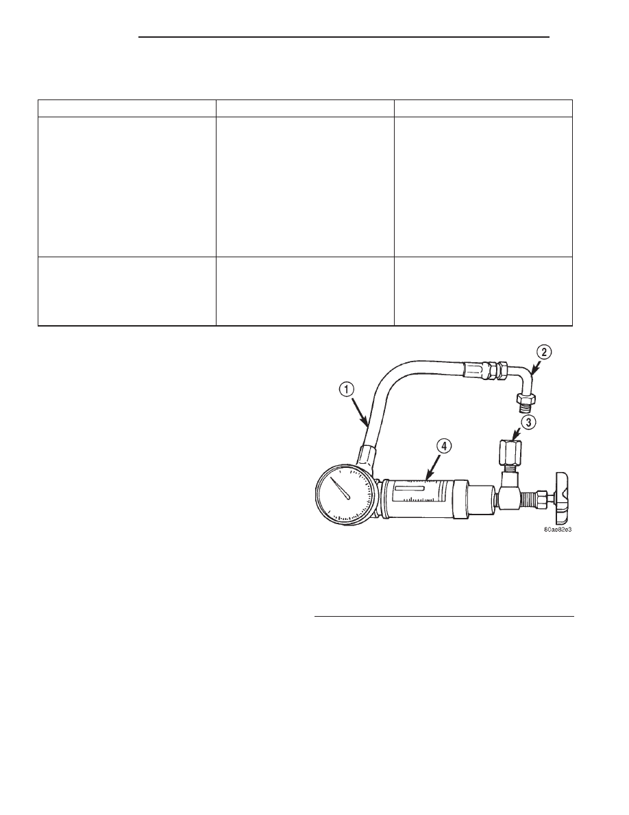
ing pressure and flow test is performed using Power
Steering Analyzer Tool kit 6815 (Fig. 3) and (Fig. 4)
Adapter Kit 6893.

FLOW AND PRESSURE TEST

(1) Check the power steering belt to ensure it is in

good condition and adjusted properly.

(2) Connect pressure gauge hose from the Power

Steering Analyzer to Tube 6844.

(3) Connect Adapter 6826 to Power Steering Ana-

lyzer test valve end.

(4) Disconnect the high pressure hose from the

power steering pump.

(5) Connect the tube to the pump hose fitting.
(6) Connect the power steering hose from the

steering gear to the adapter.

(7) Open the test valve completely.
(8) Start engine and let idle long enough to circu-

late power steering fluid through flow/pressure test
gauge and to get air out of the fluid. Then shut off
engine.

(9) Check fluid level, add fluid as necessary. Start

engine again and let idle.

(10) Gauge should read below 862 kPa (125 psi), if

above, inspect the hoses for restrictions and repair as
necessary. The initial pressure reading should be in
the range of 345-552 kPa (50-80 psi).

(11) Increase the engine speed to 1500 RPM and

read the flow meter. If the flow rate (GPM) is below
specification, (refer to pump specification chart for
GPM) the pump should be replaced.

Fig. 3 Analyzer With Tube and Adapter For 5.2L &

5.9L

1 – GAUGE HOSE
2 – TUBE
3 – ADAPTER FITTINGS
4 – ANALYZER

19 - 4

STEERING

DN

DIAGNOSIS AND TESTING (Continued)

CAUTION: The following test procedure involves
testing maximum pump pressure output and flow
control valve operation. Do not leave valve closed
for more than three seconds as the pump could be
damaged.

(12) Close valve fully three times and record high-

est pressure indicated each time. All three read-
ings must be above specifications and within
345 kPa (50 psi) of each other.

• Pressures above specifications but not within

345 kPa (50 psi) of each other, replace pump.

• Pressures within 345 kPa (50 psi) of each other

but below specifications, replace pump.

(13) Open the test valve and turn the steering

wheel to the extreme left and right positions three
times against the stops. Record the highest pressure
reading at each position. Compare readings to the
pump specifications chart. If pressures readings are
not within 50 psi of each other, the gear is leaking
internally and must be replaced.

CAUTION: Do

not

force

the

pump

to

operate

against the stops for more than 2 to 3 seconds at a
time because, pump damage will result.

Fig. 4 Analyzer With Tube and Adapter For 4.7L

1 – TUBE
2 – ADAPTER FITTINGS
3 – ANALYZER
4 – GAUGE HOSE

PUMP SPECIFICATION

ENGINE

RELIEF PRESSURE

6

50

FLOW RATE

(GPM) AT 1500

RPM

5.2L

10342 kPa (1500 psi)

2.4 - 2.8

4.7L

10342 kPa (1450 psi)

2.4 - 2.8

5.9L

10342 kPa (1500 psi)

2.4 - 2.8

DN

STEERING

19 - 5

DIAGNOSIS AND TESTING (Continued)

POWER STEERING PUMP

TABLE OF CONTENTS

page

page

DESCRIPTION AND OPERATION

POWER STEERING PUMP . . . . . . . . . . . . . . . . . . 6

DIAGNOSIS AND TESTING

PUMP LEAKAGE . . . . . . . . . . . . . . . . . . . . . . . . . . 7

SERVICE PROCEDURES

POWER STEERING PUMP - INITIAL

OPERATION . . . . . . . . . . . . . . . . . . . . . . . . . . . . 7

REMOVAL AND INSTALLATION

POWER STEERING PUMP - 5.2L & 5.9L . . . . . . . . 7

POWER STEERING PUMP - 4.7L. . . . . . . . . . . . . . 8

DISASSEMBLY AND ASSEMBLY

PUMP PULLEY . . . . . . . . . . . . . . . . . . . . . . . . . . . 9

SPECIFICATIONS

TORQUE CHART . . . . . . . . . . . . . . . . . . . . . . . . . . 9

SPECIAL TOOLS

POWER STEERING PUMP . . . . . . . . . . . . . . . . . . 9

DESCRIPTION AND OPERATION

POWER STEERING PUMP

DESCRIPTION

The pump is connected to the steering gear via the

pressure hose and the return hose. The pump shaft
has a pressed-on pulley that is belt driven by the
crankshaft pulley.

Trailer tow option vehicles are equipped with a

power steering pump oil cooler. On the 5.2L and 5.9L
the oil cooler is mounted to the engine block. On the
4.7L the oil cooler is mounted to the power steering
pump.

NOTE: Power steering pumps are not interchange-
able with pumps installed on other vehicles.

OPERATION

Hydraulic pressure is provided for the power steer-

ing gear by the belt driven power steering pump (Fig.
1) and (Fig. 2). The power steering pumps are con-

stant flow rate and displacement, vane-type pumps.

Fig. 1 Power Steering Pump - 5.2L & 5.9L

1 – RESERVOIR CAP AND DIPSTICK
2 – RESERVOIR

19 - 6

STEERING

DN

DIAGNOSIS AND TESTING

PUMP LEAKAGE

The pump is serviced as an assembly and should

not be disassembled. Plastic pump reservoirs can be
replace and the reservoir O-ring.

Check for leaks in the following areas:
• Pump shaft seal behind the pulley

• Pump to reservoir O-ring

• Reservoir cap

• Pressure and return lines

• Flow control valve fitting

SERVICE PROCEDURES

POWER STEERING PUMP - INITIAL
OPERATION

WARNING: THE

FLUID

LEVEL

SHOULD

BE

CHECKED WITH ENGINE OFF TO PREVENT INJURY
FROM MOVING COMPONENTS.

CAUTION: Use MOPAR Power Steering Fluid or
equivalent. Do not use automatic transmission fluid
and do not overfill.

Wipe filler cap clean, then check the fluid level.

The dipstick should indicate COLD when the fluid is
at normal temperature.

(1) Turn steering wheel all the way to the left
(2) Fill the pump fluid reservoir to the proper level

and let the fluid settle for at least two (2) minutes.

(3) Raise the front wheels off the ground.
(4) Slowly turn the steering wheel lock-to-lock 20

times with the engine off while checking the fluid
level.

NOTE: Vehicles with long return lines or oil coolers
turn wheel 40 times.

(5) Start the engine. With the engine idling main-

tain the fluid level.

(6) Lower the front wheels and let the engine idle

for two minutes.

(7) Turn the steering wheel in both direction and

verify power assist and quiet operation of the pump.

If the fluid is extremely foamy or milky looking,

allow the vehicle to stand a few minutes and repeat
the procedure.

CAUTION: Do not run a vehicle with foamy fluid for
an extended period. This may cause pump damage.

REMOVAL AND INSTALLATION

POWER STEERING PUMP - 5.2L & 5.9L

REMOVAL

(1) Remove the serpentine drive belt, refer to

Group 7 Cooling.

(2) Clamp the fluid return hose and disconnect the

hoses from the power steering pump. Cap the fit-
tings.

(3) Remove battery ground cable and bracket bolts.
(4) Remove the pump assembly (Fig. 3).
(5) Remove the pump pulley, refer to Pump Pulley

Removal. This will allow access to the pump attach-
ing screws.

(6) Remove the pump bracket bolts (Fig. 4) and

remove the bracket.

INSTALLATION

(1) Install the bracket on the pump and tighten

bolts to 41 N·m (30 ft. lbs.).

(2) Install the pump pulley, refer to Pump Pulley

Installation.

(3) Install pump assembly on the engine block and

tighten the bolts to 41 N·m (30 ft. lbs.).

(4) Install the battery ground wire and tighten nut

to 41 N·m (30 ft. lbs.).

(5) Connect the fluid hoses to the pump.

Fig. 2 Power Steering Pump - 4.7L

1 – PUMP
2 – RESERVOIR
3 – PULLEY

DN

STEERING

19 - 7

DESCRIPTION AND OPERATION (Continued)


Content   ..  21  22  23  24   ..