Dodge Dakota (ND). Manual - part 332
*DRIVER DOOR LOCK/UNLOCK SWITCH INPUT CIRCUIT LOW (CONTINUED)
For the Power Door Lock circuit diagram (Refer to 8 - ELECTRICAL/POWER LOCKS - SCHEMATICS AND DIA-
GRAMS)
For a complete wiring diagram Refer to Section 8W.
Possible Causes
(G161) DRIVER DOOR LOCK SWITCH MUX CIRCUIT SHORT TO GROUND
DOOR LOCK SWITCH SHORT TO GROUND
INSTRUMENT CLUSTER
Diagnostic Test
1.
TEST FOR TROUBLE CODES
Turn the ignition on.
With the scan tool, read DTC’s
Does the scan tool display any Body related DTC’s?
No
>> Go To 2
Yes
>> Refer to the symptom list and repair any DTC’s before
proceeding.
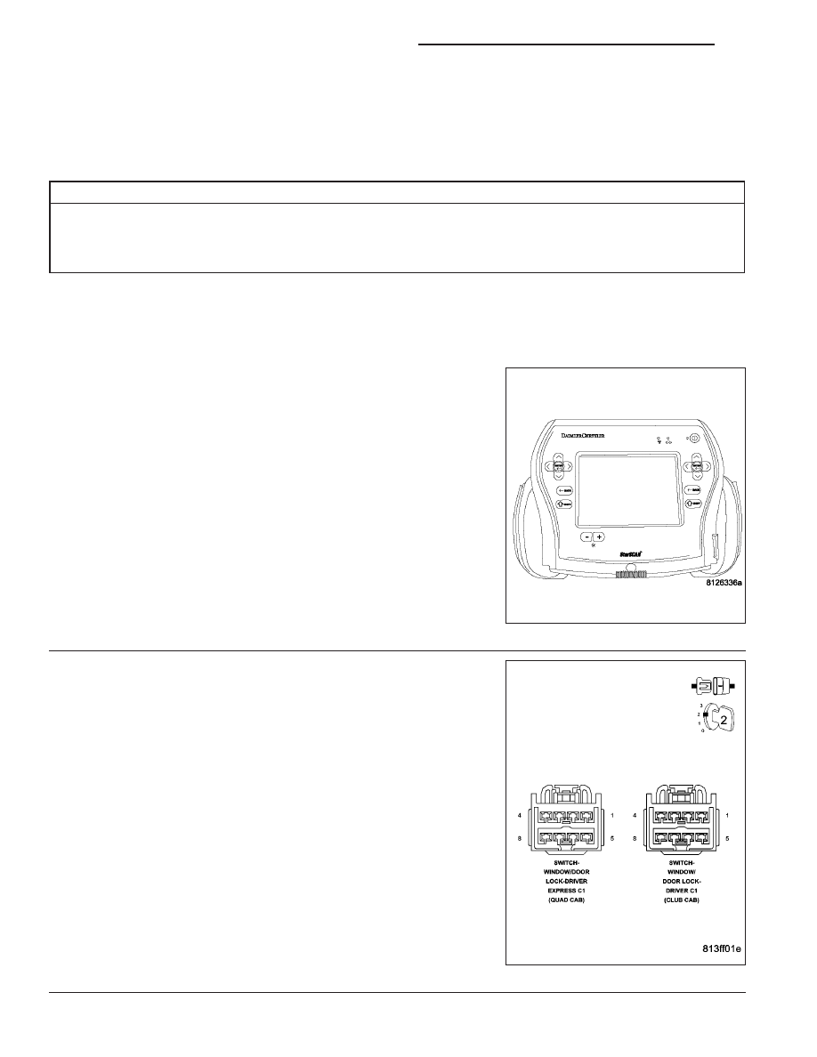
2.
DOOR LOCK SWITCH SHORTED
Disconnect the Driver Window/Door Lock Switch connector.
With the scan tool in sensors, read the DRIVER DOOR LOCK
SWITCH voltage.
Is the voltage approximately 5.0?
Yes
>> Replace the Driver Window/Door Lock Switch.
Perform BODY VERIFICATION TEST - VER 1. (Refer to 8
- ELECTRICAL/POWER LOCKS - DIAGNOSIS AND
TESTING)
No
>> Go To 3
8N - 4
POWER LOCKS - ELECTRICAL DIAGNOSTICS
ND