Dodge Dakota (ND). Manual - part 240
11. Raise the vehicle on a hoist, (Refer to LUBRICA-
TION & MAINTENANCE/HOISTING - STANDARD
PROCEDURE)
12. Remove the left front fender liner, (Refer to 23 -
BODY/EXTERIOR/LF
WHEELHOUSE
SPLASH
SHIELD - DESCRIPTION).
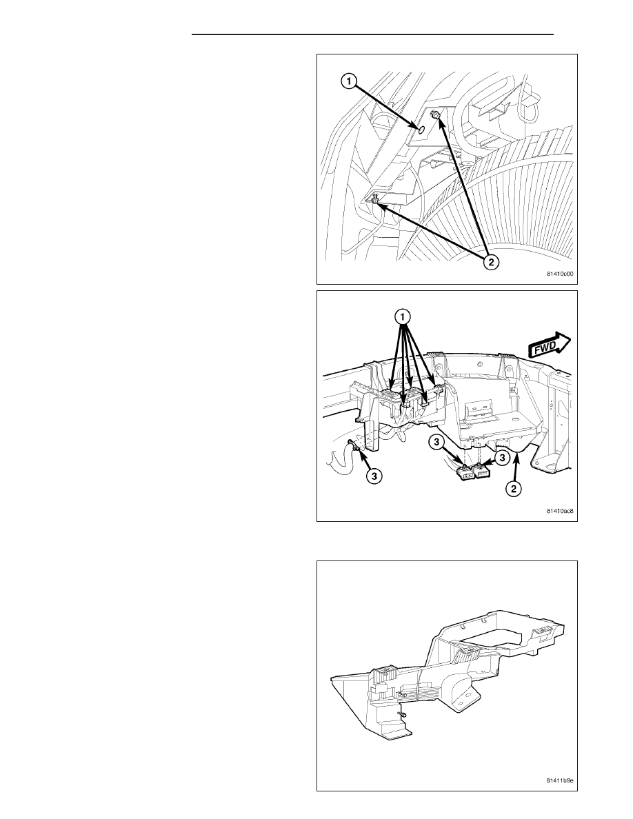
NOTE: The middle bolt hole is to remain open for
a front fender liner fastener (1).
13. Remove the lower battery tray mounting bolts (2).
14. Lower the vehicle.
15. Remove the battery tray (2) from the vehicle.
INSTALLATION
1. Clean and inspect the battery tray, (Refer to 8 -
ELECTRICAL/BATTERY SYSTEM - CLEANING).
8F - 30
BATTERY SYSTEM
ND