Dodge Dakota (ND). Manual - part 68
NOTE: Prior to installing the master cylinder assembly check that there is a vacuum seal present at the
shoulder of the master cylinder flange and it’s neck. A square seal must be present to ensure vacuum integ-
rity with the booster.
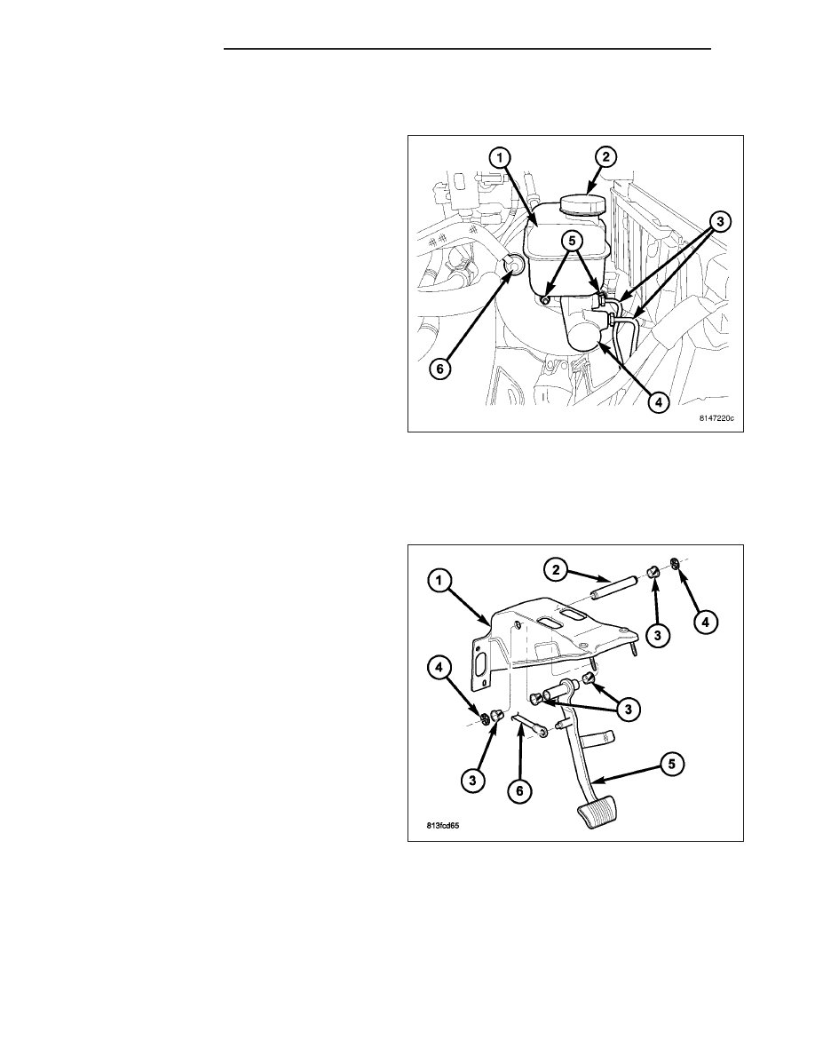
1. Gently install the master cylinder (4) on the booster
mounting studs (5).
NOTE: Take precautions to locate the master cyl-
inder plunger over the booster output rod, before
installing the master cylinder. If correctly fitted the
master cylinder should slide easily onto the
booster output rod before the mounting studs are
engaged in the flange holes of the master cylinder.
2. Install new mounting nuts (5) and tighten to 10 N·m
(90 in. lbs.)
3. Install the brake lines (3) and tighten to 19 N·m
(170 in. lbs.).
4. Reconnect the electrical connector for the low fluid
level switch.
5. Fill and bleed the base brake system. (Refer to 5 -
BRAKES - STANDARD PROCEDURE).
PEDAL
DESCRIPTION
NOTE: The brake pedal is serviced as a complete
assembly including the bracket.
A suspended-type brake pedal (5) is used. The pedal
is attached to the pedal support bracket (1) with a
pivot shaft pin (2), bushings (3) and clips (4). If the
bushings (3) become dry a spray lubricant can be
used to eliminate noises. The booster push rod is
attached to the pedal with a clip. The pedal (5), bush-
ings (3), pivot pin (2) and support bracket (1) are not
serviceable components.
OPERATION
The brake pedal is attached to the booster push rod. When the pedal is depressed, the primary booster push rod
is depressed which move the booster secondary rod. The booster secondary rod depress the master cylinder piston.
REMOVAL
WARNING: BEFORE SERVICING THE STEERING COLUMN THE AIRBAG SYSTEM MUST BE DISARMED.
REFER TO ELECTRICAL RESTRAINT SYSTEM FOR SERVICE PROCEDURES. FAILURE TO DO SO MAY
RESULT IN ACCIDENTAL DEPLOYMENT OF THE AIRBAG AND POSSIBLE PERSONAL INJURY.
5 - 42
BRAKES - BASE
ND