Chrysler Le Baron, Dodge Dynasty, Plymouth Acclaim. Manual - part 285


  Index      Dodge     Chrysler Le Baron, Dodge Dynasty, Plymouth Acclaim - service repair manual 1993 year


Search            


Content   ..  283  284  285  286   ..


Chrysler Le Baron, Dodge Dynasty, Plymouth Acclaim. Manual - part 285


Light scaling of the terminals can be cleaned with

a sharp knife. If the terminals are heavily scaled, re-
place the distributor cap.

A cap that is greasy, dirty or has a powder-like

substance on the inside should be cleaned with a so-
lution of warm water and a mild detergent. Scrub
the cap with a soft brush. Thoroughly rinse the cap
and dry it with a clean soft cloth.

ROTOR

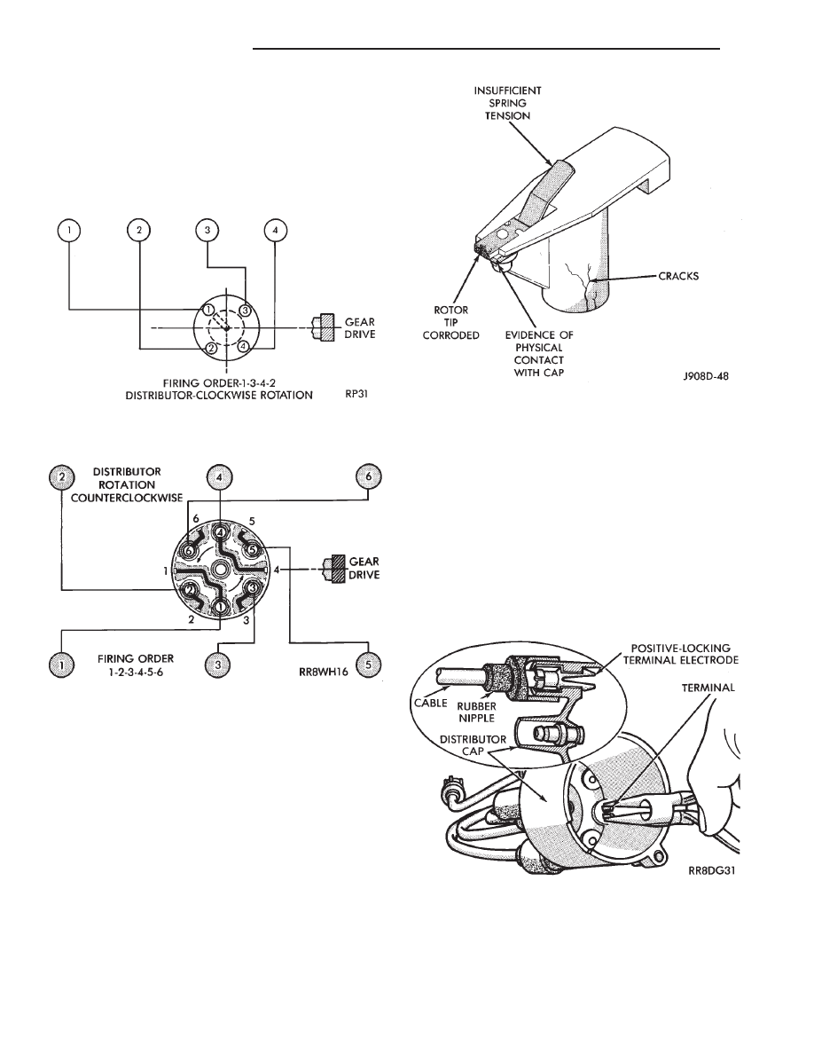
Replace the rotor if it is cracked, the tip is exces-

sively burned or heavily scaled (Fig. 4). If the spring
terminal does not have adequate tension, replace the
rotor.

SPARK PLUG CABLES

Spark Plug cables are sometimes referred to as sec-

ondary ignition wires. They transfer electrical cur-
rent from the distributor to individual spark plugs at
each cylinder. 2.2L TBI, 2.5L TBI, 2.5L MPI, Turbo
III and 3.0L engines use resistance type cables. The
cables suppress radio frequency emissions from the
ignition system.

Check the spark plug cable connections for good

contact at the coil and distributor cap towers and at
the spark plugs. Terminals should be fully seated.
The nipples and spark plug covers should be in good

condition. Nipples should fit tightly on the coil and
distributor cap towers and spark plug cover should fit
tight around spark plug insulators. Loose cable connec-
tions can cause ignition malfunctions by permitting
water to enter the towers, corroding, and increasing
resistance. To maintain proper sealing at the ter-
minal connections, the connections should not
be broken unless testing indicates high resis-
tance, an open circuit or other damage.

CAUTION: Do not pull spark plug cables from dis-
tributor cap of four cylinder engines. The cables must
be released from inside the distributor cap (Fig. 5).

Clean high tension cables with a cloth moistened

with a non-flammable solvent and wipe dry. Check for
brittle or cracked insulation.

Fig. 2 Engine Firing Order—2.2L TBI, 2.5L TBI, 2.5L

MPI and Turbo III Engines

Fig. 3 Engine Firing Order—3.0L Engine

Fig. 4 Rotor Inspection—Typical

Fig. 5 Spark Plug Cable Removal/Installation—2.2L

and 2.5L TBI Engines

8D - 2

IGNITION SYSTEMS

Ä

When testing secondary cables for punctures and

cracks with an oscilloscope follow the equipment
manufacturers instructions.

If an oscilloscope is not available, secondary cables

can be tested as follows:

CAUTION: Do not leave any one spark plug cable
disconnected any longer than necessary during test-
ing. Excessive heat could damage the catalytic con-
verter. Total test time must not exceed ten minutes.

(a) With the engine not running, connect one end

of a test probe to a good ground. Use a probe made of
insulated wire with insulated alligator clips on each
end.

(b) With engine running, move test probe along

entire length of all cables (approximately 0 to 1/8
inch gap). If punctures or cracks are present there
will be a noticeable spark jump from the faulty area
to the probe. Check the coil cable the same way.
Replace cracked, leaking or faulty cables.
When replacing cables, install the new high

tension cable and nipple assembly over cap or
coil tower. When entering the terminal into the
tower, push lightly, then pinch the large diam-
eter of nipple to release air trapped between the
nipple and tower. Continue pushing on the cable
and nipple until cables are properly seated in the
cap towers. A snap should be heard as terminal
goes into place.

Use the same procedure to install cable in coil tower.

Wipe the spark plug insulator clean before reinstalling
cable and cover.

Use the following procedure when removing the high

tension cable from the spark plug. First, remove the
cable from the retaining bracket. Then grasp the ter-
minal as close as possible to the spark plug. Rotate the
cover and pull the cable straight back. Pulling on the
cable itself will damage the conductor and termi-
nal connection. Do not use pliers and do not pull
the cable at an angle. Doing so will damage the
insulation, cable terminal or the spark plug in-
sulator. Wipe spark plug insulator clean before
reinstalling cable and cover.

Resistance type cable is identified by the words

Electronic Suppression printed on the cable jacket.

Use an ohmmeter to check resistance type cable for

open circuits, loose terminals or high resistance as
follows:

(a) Remove cable from spark plug.
(b) Lift distributor cap from distributor with

cables intact. Do not remove cables from cap. The
cables must be removed from the spark plugs.

(c) Connect the ohmmeter between spark plug end

terminal and the corresponding electrode inside the
cap, make sure ohmmeter probes are in good contact.
Resistance should be within tolerance

shown in the cable resistance chart. If resistance is
not within tolerance, remove cable at cap tower
and check the cable. If resistance is still not within
tolerance, replace cable assembly. Test all spark
plug cables in same manner.

To test coil to distributor cap high tension cable,

remove distributor cap with the cable intact. Do not
remove cable from the cap. 
Connect the ohmmeter
between center contact in the cap and remove the ca-
ble at coil tower and check cable resistance. If resis-
tance is not within tolerance, replace the cable.

SPARK PLUGS

Resistor spark plugs are used in all engines and

have resistance values of 6,000 to 20,000 ohms when
checked with at least a 1000 volt tester.

Remove the spark plugs and examine them for

burned electrodes and fouled, cracked or broken por-
celain insulators. Keep plugs arranged in the order
in which they were removed from the engine. An iso-
lated plug displaying an abnormal condition indi-
cates that a problem exists in the corresponding
cylinder. Replace spark plugs at the intervals recom-
mended in Group O.

Undamaged low milage spark plugs can be cleaned

and reused. Refer to the Spark Plug Condition sec-
tion of this group. After cleaning, file the center elec-
trode flat with a small point file or jewelers file.
Adjust the gap between the electrodes (Fig. 6) to the
dimensions specified in the chart at the end of this
section.

Always tighten spark plugs to the specified torque.

Over tightening can cause distortion and change
spark plug gap. Tighten spark plugs to 28 N

Im (20 ft.

lbs.) torque.

SPARK PLUG CONDITION

NORMAL OPERATING CONDITIONS

The few deposits present will be probably light tan

or slightly gray in color with most grades of commer-
cial gasoline (Fig. 7). There will not be evidence of
electrode burning. Gap growth will not average more
than approximately 0.025 mm (.001 in) per 1600 km
(1000 miles) of operation. Spark plugs that have nor-
mal wear can usually be cleaned, have the electrodes
filed and regapped, and then reinstalled.

Some fuel refiners in several areas of the United

States have introduced a manganese additive (MMT)

CABLE RESISTANCE CHART

Ä

IGNITION SYSTEMS

8D - 3

for unleaded fuel. During combustion, fuel with
MMT coats the entire tip of the spark plug with a
rust color deposit. The rust color deposits could be
misdiagnosed as being caused by coolant in the com-
bustion chamber. MMT deposits do not affect spark
plug performance.

COLD FOULING (CARBON FOULING)

Cold fouling is sometimes referred to as carbon

fouling. The deposits that cause cold fouling are ba-
sically carbon (Fig. 7). A dry, black deposit on one or
two plugs in a set may be caused by sticking valves
or defective spark plug cables. Cold (carbon) fouling
of the entire set may be caused by a clogged air
cleaner.

Cold fouling is normal after short operating periods.

The spark plugs do not reach a high enough operating
temperature during short operating periods.

WET FOULING

A spark plug that is coated with excessive wet fuel or

oil is wet fouled. In older engines, wet fouling can be
caused by worn rings or excessive cylinder wear.
Break-in fouling of new engines may occur be-
fore normal oil control is achieved. In new or
recently overhauled engines, wet fouled spark
plugs can be usually be cleaned and reinstalled.

OIL OR ASH ENCRUSTED

If one or more plugs are oil or oil ash encrusted,

engine oil is entering the combustion chambers (Fig. 8).
Evaluate the engine to determine the cause.

HIGH SPEED MISS

When replacing spark plugs because of a high speed

miss condition; wide open throttle operation
should be avoided for approximately 80 km (50
miles) after installation of new plugs. 
This will
allow deposit shifting in the combustion chamber to
take place gradually and avoid plug destroying splash
fouling shortly after the plug change.

ELECTRODE GAP BRIDGING

Loose deposits in the combustion chamber can cause

electrode gap bridging. The deposits accumulate on the
spark plugs during continuous stop-and-go driving.
When the engine is suddenly subjected to a high torque
load, the deposits partially liquefy and bridge the gap
between the electrodes

Fig. 6 Setting Spark Plug Electrode Gap—Typical

Fig. 7 Normal Operation and Cold (Carbon) Fouling

Fig. 8 Oil or Ash Encrusted

8D - 4

IGNITION SYSTEMS

Ä

(Fig. 9). This short circuits the electrodes. Spark
plugs with electrode gap bridging can be cleaned us-
ing standard procedures.

SCAVENGER DEPOSITS

Fuel scavenger deposits may be either white or yel-

low (Fig. 10). They may appear to be harmful, but
are a normal condition caused by chemical additives
in certain fuels. These additives are designed to
change the chemical nature of deposits and decrease
spark plug misfire tendencies. Accumulation on the
ground electrode and shell area may be heavy but
the deposits are easily removed. Spark plugs with
scavenger deposits can be considered normal in con-
dition and be cleaned using standard procedures.

CHIPPED ELECTRODE INSULATOR

A chipped electrode insulator usually results from

bending the center electrode while adjusting the
spark plug electrode gap. Under certain conditions,
severe detonation also can separate the insulator
from the center electrode (Fig. 11). Replace spark
plugs with chipped electrode insulators.

PREIGNITION DAMAGE

Excessive combustion chamber temperature can

cause preignition damage. The center electrode dis-
solves first and the ground electrode dissolves some-
what later (Fig. 12). Insulators appear relatively
deposit free. Determine if the spark plug has the cor-
rect heat range rating for the engine, if ignition tim-
ing is over advanced or if other operating conditions
are causing engine overheating. The heat range rat-
ing refers to the operating temperature of a particu-
lar type spark plug. Spark plugs are designed to
operate within specific temperature ranges depend-
ing upon the thickness and length of the center elec-
trode and porcelain insulator.

SPARK PLUG OVERHEATING

Overheating is indicated by a white or gray center

electrode insulator that also appears blistered (Fig.
13). The increase in electrode gap will be consider-
ably in excess of 0.001 in per 1000 miles of operation.
This suggests that a plug with a cooler heat range
rating should be used. Over advanced ignition tim-

Fig. 9 Electrode Gap Bridging

Fig. 10 Scavenger Deposits

Fig. 11 Chipped Electrode Insulator

Fig. 12 Preignition Damage

Ä

IGNITION SYSTEMS

8D - 5


Content   ..  283  284  285  286   ..