Chrysler Le Baron, Dodge Dynasty, Plymouth Acclaim. Manual - part 60


  Index      Dodge     Chrysler Le Baron, Dodge Dynasty, Plymouth Acclaim - service repair manual 1993 year


Search            


Content   ..  58  59  60  61   ..


Chrysler Le Baron, Dodge Dynasty, Plymouth Acclaim. Manual - part 60


(11) Verify the hoses are securely attached to the

vapor canister (Fig. 8).

(12) Ensure the harness connectors for the fuel in-

jector are attached to the correct injector and not
damaged.

(13) Verify the fuel injector harness and engine

wiring harness connectors are fully inserted into the
main wiring harness.

(14) Check the vacuum connections at the throttle

body (Fig. 9).

(15) Ensure the idle air control motor and TPS

electrical connectors are fully seated and not dam-
aged (Fig. 9).

(16) Verify the harness connector is attached to

the electric EGR transducer solenoid (Fig. 9).

(17) Verify the vacuum connections at the trans-

ducer are secure (Fig. 9). Check all EGR system vac-
uum hoses for secure connections. Inspect the EGR
tube.

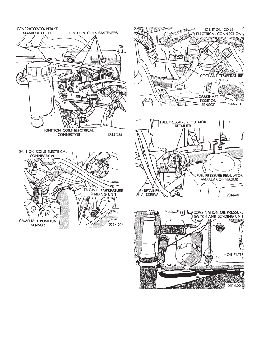
Fig. 2 Ignition Coils Electrical Connection

Fig. 3 Camshaft Position Sensor

Fig. 4 Engine Coolant Temperature Sensor

Fig. 5 Fuel Pressure Regulator Vacuum Connection

Fig. 6 Oil Pressure Sending Unit Electrical

Connection

14 - 158

FUEL SYSTEMS

Ä

(18) Inspect the park/neutral switch wiring connec-

tion for damage. Ensure the automatic transaxle
electrical connections are not damaged (Fig. 10).

(19) Check the Vacuum Hose Harness connections

at the Intake Plenum (Fig. 11).

(20) Inspect the PCV system connections for dam-

age (Fig. 12).

(21) Inspect the crankshaft position sensor electri-

cal connector for damage (Fig. 13).

(22) Ensure the vehicle speed sensor electrical con-

nector is attached to the sensor and not damaged
(Fig. 13).

(23) Verify the manifold absolute pressure (map)

sensor electrical connector is attached to the sensor
and not damaged (Fig. 14).

(24) Verify the engine ground strap is attached at

the engine (below the MAP sensor) and dash panel
(Fig. 14). Inspect the strap for corrosion or damage.

Fig. 10 Automatic Transaxle Electrical Connections

Fig. 11 Vacuum Hose Connections

Fig. 7 Canister Purge Solenoid

Fig. 8 Vapor Canister

Fig. 9 Throttle Body Electrical and Vacuum

Connections

Ä

FUEL SYSTEMS

14 - 159

(25) Check the heated oxygen sensor electrical con-

nector for damage (Fig. 14).

(26) Inspect the generator wiring connections for

damage.

(27) Check the accessory drive belt tension.
(28) Check the 60-way electrical connection at the

PCM (Fig. 15) for damage or spread terminals. Ver-
ify that the 60-way connector is fully inserted into
the PCM socket. Ensure the wires are not stretched
or pulled out of the connector.

(29) Check for full insertion of the relays in the

power distribution center (Fig. 16).

(30) Check battery cable connections.
(31) Check the power brake booster hose connec-

tion (without Anti-lock Brake Systems) (Fig. 17).

(32) Check the speed control vacuum connection

(Fig. 18).

(33) Inspect hose and wiring connections at fuel

pump. Check that wiring connector is making con-
tact with terminals on pump.

Fig. 12 PCV System

Fig. 13 Crankshaft Position Sensor and Vehicle

Speed Sensor

Fig. 14 MAP Sensor and Heated Oxygen Sensor

Fig. 15 Powertrain Control Module (PCM)

Fig. 16 Power Distribution Center

14 - 160

FUEL SYSTEMS

Ä

Fig. 17 Power Brake Booster Hose

Fig. 18 Speed Control Vacuum

Ä

FUEL SYSTEMS

14 - 161


Content   ..  58  59  60  61   ..