Daewoo Musso. Manual - part 295


  Index      Daewoo     Daewoo Musso - service repair manual


Search            


Content   ..  293  294  295  296   ..


Daewoo Musso. Manual - part 295


TRANSFER CASE (PART TIME 4408)  5D1-19

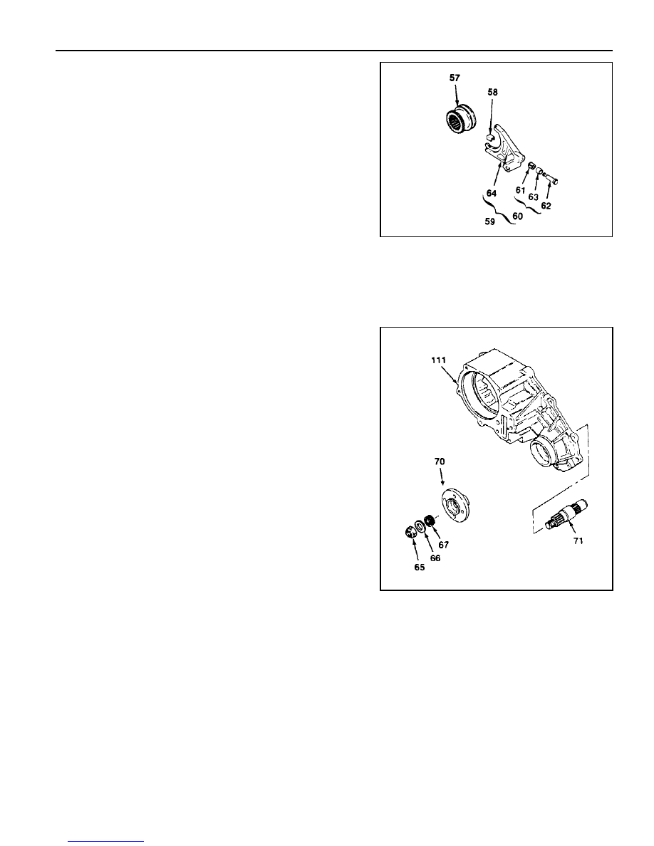
<Front Output Assembly>

1. Holding the companion flange, remove the nut and washer

and then remove the companion flange and oil seal.

2. Remove the output shaft.

65 Nut
66 Washer
67 Oil Seal
70 Companion Flange
71 Output Shaft (front)

111 Case

57

Reduction Hub

58

Shift Fork Facing

59

Reduction Shift Fork Assembly

60

Roller Pin and Retainer Assembly

61

Retainer

62

Pin

63

Roller Cam

64

Reduction Shift Fork

<Reduction Shift Parts>

1. Remove the reduction hub and reduction shift fork assembly

from the case.

2. Remove the 2 shill fork facings from the shift fork assembly.

3. To remove the roller cam and pin, cut elf the plastic retainer

when disassembling the fork assembly.

5D1-20  TRANSFER CASE (PART TIME 4408)

<Adapter, Input Shaft and Carrier Gear>

72 Breather
73 Bolt
74 Adapter Assembly
75 Snap Ring
76 Oil Seal
77 Spiral Pin
78 Front Adapter
79 Retaining Ring
80 Bearing
81 Input Shaft Assembly

1. Remove the breather.

2. After removing 6 bolts, remove the front adopter by

separating the adapter sealer bond from the case
using a screw driver.

Notice

Be careful not to damage the contacting surface of
the case and adapter.

3. Remove the adapter assembly, input shaft assembly

and carrier gear assembly.

4. Remove the snap ring and oil seal from the front

adapter.

5. After removing snap ring, pull out the bearing and

thrust washer from the input shaft assembly and
separate the input shaft assembly from the carrier
gear assembly.

6. Remove the needle bearing and sleeve bearing from

the input shaft assembly.

7. Remove the retaining ring, thrust plate rind sun gear

from the planet carrier assembly.

Notice

Do not disassemble the planet carrier assembly.

82 Sleeve Bearing
83 Needle Bearing
84 Input Shaft
85 Thrust Bearing
86 Carrier Gear Assembly
87 Retaining Ring
88 Thrust Plate
89 Sun Gear
90 Planet Carrier Assembly

111 Case

TRANSFER CASE (PART TIME 4408)  5D1-21

<Electric Shifts Cam Parts>

1. Remove the electric shift cam parts from the case assembly.

2. Separate the electric shift cam from the shift shaft.

3. Holding the shift shaft in a vise, remove the torsion spring

and spacer from the shift shaft using a screw driver.

100

Electric Shift Cam

101

Torsion Spring

102

Spacer

103

Shift Shaft

111

Case

105

Transfer Case Assembly

106

Oil Seal

107

Retaining Ring

108

Ball Bearing

119

Pin

110

Ring Gear

111

Case

<Case Assembly>

1. Remove the oil seal.

2. Remove the retaining ring and bearing.

3. Remove the pin from the transfer case.

Notice

Be careful not to damage the pin.

4. Using a press, remove the ring gear from the case.

5D1-22  TRANSFER CASE (PART TIME 4408)

Cleaning Procedure

Notice

Before cleaning, check the magnet for the

presence of metal particles which indicate internal

chipping of the transfer case.

1. Using cleaning solvent, clean the residual oil and dirt

deposits.

Notice

During cleaning, be careful not to damage the metal
surfaces.

2. After cleaning, dry the parts with low pressure (Max. 20 psi)

compressed air.

3. Lubricate the ball bearings and needle bearings with transfer

case oil after cleaning.

Notice

Protect the lubricated bearings from dust.

Inspection Procedure

1. Visually check the all removed parts.

Notice

Always replace the hose coupling, O-ring and oil seal with
new parts.

2. Inspection Terms

l

Burr : Local rise of material forming protruding sharp

edge

l

Chip : An area from which a small fragment has been

broken off or cut

l

Crack : Surface break of line nature indicating partial or

complete separation of material.

l

Excessive wear : Heavy or obvious wear beyond

expectations considering conditions of operation.

l

Indentation : Displacement of material caused by localized

heavy contact.

l

Galling : Breakdown of metal surface due to excessive

friction between parts. Particles of the softer material
are torn loose and welded to the harder material.

l

Nick : Local break or notch, usually displacement of

material rather than loss.

l

Scoring : Tear or break in metal surface from contact

under abnormal pressure.

l

Step wear : Heavy wear that produces a step that can

be seen or felt between adjacent contact and noncontact
surfaces.

l

Uneven wear : Condition of localized, unevenly distributed

wear Includes hollows, shiny spots, uneven polish and
other visual indications.


Content   ..  293  294  295  296   ..