Daewoo Musso. Manual - part 203


  Index      Daewoo     Daewoo Musso - service repair manual


Search            


Content   ..  201  202  203  204   ..


Daewoo Musso. Manual - part 203


2A-6  SUSPENSION DIAGNOSIS

DAMPING FORCE CONTROL LOGIC

Control Logic that applies on damping force variable suspension is comprised of road sensing driving comfort control
logic to increase driving comfort and vehicle speed sensing control logic, anti-roll control logic and anti-dive control
logic to secure control safety.
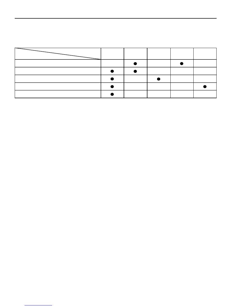
Logic

Sensor

Road Sensing Driving Comfort Control Logic

Speed

Vertical

Sensor (2.5g)

Lateral

Sensor (1g)

Axle

Acceleration

Sensor (10g)

Brake

Anti-bounce Control Logic

Anti-roll Control Logic

Anti-dive Control Logic

Vehicle Speed Sensing Control Logic

NORMAL CONTROL

Initial Stage

When ignition switch is "ON", system initialization will be performed for approx. 3 seconds. During this time, warning
lamp will stay ON and damping force will be switched to Hard status. After 3 seconds, warning lamp will turn off and
normal control status will be restored.

Normal Damping Force Control Establishment

Damping force will have Soft

®

Medium

®

Hard status in AUTO mode and Medium

®

Hard status in SPORT mode.

When double control items are satisfied at the same time it will be Hard

®

Medium

®

Soft in order.

Normal Damping Force Control Release

Control mode release will be "Hard

®

Medium

®

Soft"or "Medium

®

Soft". In case that returned from Hard status to

Medium status during control, it will be done after elapse of setting times. Returning from Medium status to Soft status
will be done immediately without delay.

 SUSPENSION DIAGNOSIS  2A-7

SELF-DIAGNOSIS

ECS-ECU indicates ECS circuit defectives to the driver by flickering ECS indicator lamp in the meter cluster 0.5
second of interval if there are defectives.

Code

Body vertical

acceleration

sensor

Defects

When sensor output

voltage is less than

0.5-4.5V, more than

4.5V.

Judging Conditions

01

0.9 - 1.1sec.

Set Time

Sensor Voltage

³

2.0 ± 0.1V

³

3.0 ± 0.1V

Release Conditions

0.9 - 1.1sec.

Set Time

Body lateral

acceleration

sensor

When sensor output

voltage is less than

0.55±0.15V, more than

4.45±0.1V.

02

0.9 - 1.1sec.

Sensor Voltage

³

2.0 ± 0.1V

³

3.0 ± 0.1V

0.9 - 1.1sec.

Stop anti-

bounce ride

control

Remedy

Stop anti-roll

control

Axle vertical

acceleration

sensor (wheel G

sensor)

When sensor output

voltage is less than

0.5-4.5V, more than

4.5V.

03

0.9 - 1.1sec.

Sensor Voltage

³

2.0 ± 0.1V

³

3.0 ± 0.1V

0.9 - 1.1sec.

Stop ride

control

Front actuator

Check step motor

power supply detecting

circuit for open and

short.

 check for relative

connectors.

04

0.4 - 0.6sec.

IGN+ SW.

OFF

®

ON

Stop control

after returning

to the previ-

ous mode

Rear actuator

When defective detect-

ing circuit has detected

defectives during

output OFF.

05

0.4 - 0.6sec.

IGN+ SW.

OFF

®

ON

Stop control

after returning

to the previous

mode

ECU

When ECU does not

work normally.

06

0.4 - 0.6sec.

Reset

Stop control

1. Turn the ignition switch ON and if ECS system is normal, ECS indicator lamp will turn on for 3 seconds and then go

off. However if defective, ECS indicator lamp will flicker in the interval of 0.5 second continuously.

2. Identify fault code with Scanner.

2A-8  SUSPENSION DIAGNOSIS

-

ACTUATOR INSPECTION

Output position of the actuator should be changed as below when battery voltage is applied between actuator
connector terminals.

Connector

terminal

Battery Voltage

Position of The Actuator Output

Remark

1 (White)

-

2 (Black)

OPEN

3 (Red)

+

1 (White)

+

2 (Black)

-

3 (Red)

OPEN

1 (White)

OPEN

2 (Black)

+

3 (Red)

SOFT Mode

MEDIUM Mode

HARD Mode

 SUSPENSION DIAGNOSIS  2A-9

ECS CIRCUIT

SCHEMATIC AND ROUTING DIAGRAMS


Content   ..  201  202  203  204   ..