Daewoo Matiz (2003 year). Manual - part 33


  Index      Daewoo     Daewoo Matiz - service repair manual 2003 year


Search            


Content   ..  31  32  33  34   ..


Daewoo Matiz (2003 year). Manual - part 33


1F – 42  ENGINE CONTROLS
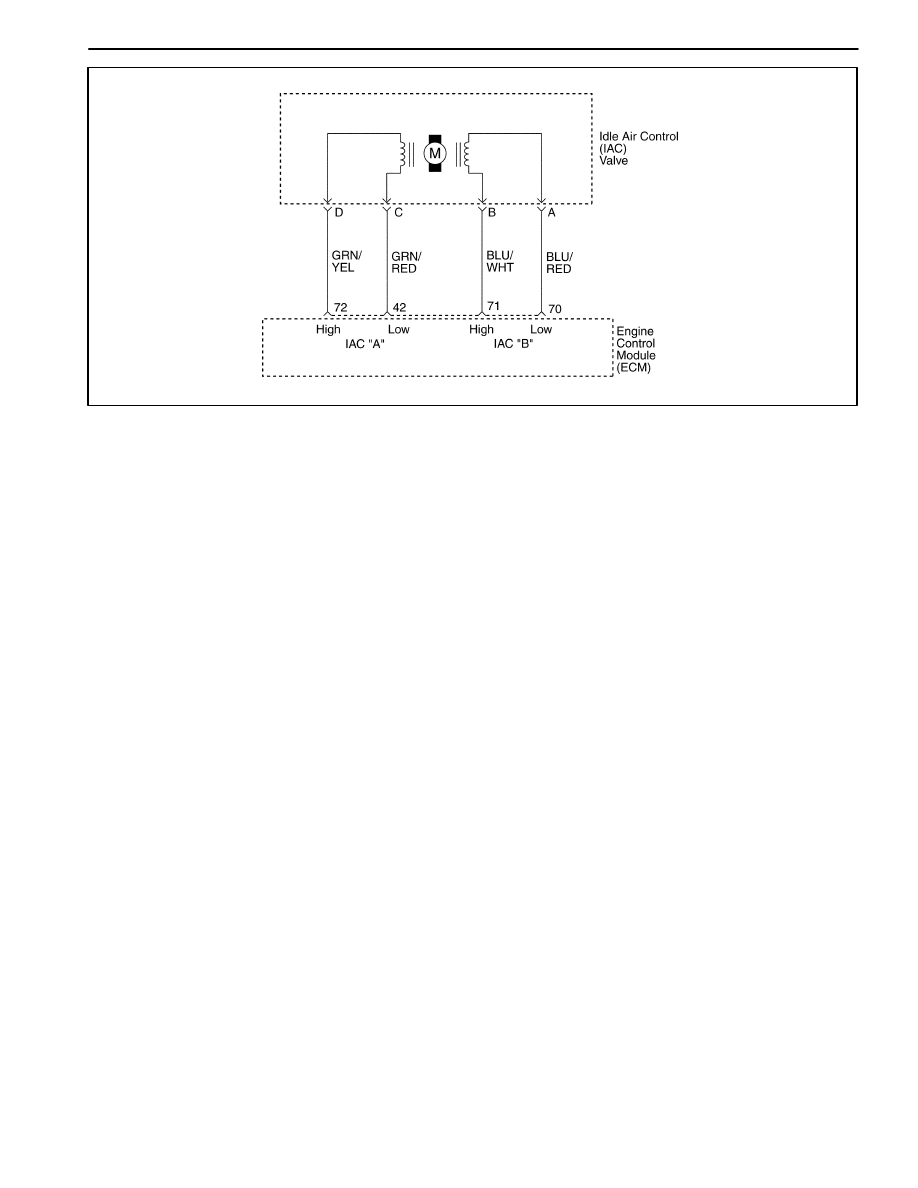
MAA1F070

IDLE AIR CONTROL SYSTEM CHECK

Circuit Description

The Engine Control Module (ECM) controls the engine
idle speed with the Idle Air Control (IAC) valve. To in-
crease the idle speed, the ECM pulls the IAC pintle
away from its seat, allowing more air to pass by the
throttle body. To decrease the idle speed, it extends the
IAC valve pintle toward its seat, reducing bypass air
flow. A scan tool will read the ECM commands to the
IAC valve in counts. The higher counts indicate more air
bypass (higher idle). The lower counts indicate less air is
allowed to bypass (lower idle).

Diagnostic Aids

If the idle is too high, stop the engine. Fully extend the
Idle Air Control (IAC) valve with a IAC driver. Start the
engine. If the idle speed is above 950 rpm, locate and
repair the vacuum leak. Also, check for a binding throttle
plate or throttle linkage or an incorrect base idle setting.

Idle Air Control Valve Reset Procedure

Whenever the battery cable or the Engine Control Mod-
ule (ECM) connector or the ECM fuse EF6 is discon-

nected or replaced, the following idle learn procedure
must be performed:

1.

Turn the ignition ON for 5 seconds.

2.

Turn the ignition OFF for 10 seconds.

3.

Turn the ignition ON for 5 seconds.

4.

Start the engine in park/neutral.

5.

Allow the engine to run until the engine coolant is
above 85

_

C (185

_

F ).

6.

Turn the A/C ON for 10 seconds, if equipped.

7.

Turn the A/C OFF for 10 seconds, if equipped.

8.

If the vehicle is equipped with an automatic trans-
axle, apply the parking brake. While pressing the
brake pedal, place the transaxle in D (drive).

9.

Turn the A/C ON for 10 seconds, if equipped.

10. Turn the A/C OFF for 10 seconds, if equipped.

11. Turn the ignition OFF. The idle learn procedure is

complete.

ENGINE CONTROLS  1F – 43

Idle Air Control System Check

Step

Action

Value(s)

Yes

No

1

Perform an Euro On-Board Diagnostic (EOBD)
system check.
Was the check performed?

Go to Step 2

Go to “Euro

On-Board

Diagnostic

System Check”

2

1. Turn the ignition OFF.
2. Remove Idle Air Control (IAC) valve.
3. Inspect the IAC passages for restrictions.
Is the problem found?

Go to Step 3

Go to Step 4

3

Clean the IAC passages.
Is the repair complete?

System OK

4

Measure the resistance between following terminals
of IAC valve.

D

Terminal A and B

D

Terminal C and D

Does the resistance equal to the value specified?

40–80 

Go to Step 6

Go to Step 5

5

Replace the IAC valve.
Is the repair complete?

System OK

6

1. Disconnect the Engine control Module (ECM)

connector.

2. Check for an open or short in the wires between

following terminals.

D

Terminal A of IAC valve connector and terminal
70 of ECM connector

D

Terminal B of IAC valve connector and terminal
71 of ECM connector

D

Terminal C of IAC valve connector and terminal
42 of ECM connector

D

Terminal D of IAC valve connector and terminal
72 of ECM connector

Is the problem found?

Go to Step 8

Go to Step 7

7

Repair an open or short circuit as needed.
Is the repair complete?

System OK

8

Inspect the IAC connector terminals and the ECM
connector terminals.
Is the problem found?

Go to Step 9

Go to Step 10

9

Repair or replace the throttle body assembly and/or
ECM connector terminals as needed.
Is the repair complete?

System OK

10

Replace the ECM.
Is the repair complete?

System OK

1F – 44  ENGINE CONTROLS

MAA1F080

IG

NI

T

IO

N

 SYST

EM

 C

H

ECK

ENGINE CONTROLS  1F – 45

IGNITION SYSTEM CHECK

Circuit Description

The Electronic Ignition (EI) system uses a waste spark
method of spark distribution. In this type of EI system,
the Crankshaft Position (CKP) sensor is mounted to the
oil pump near a slotted wheel that is a part of the crank-
shaft pulley. The CKP sensor sends reference pulses to
the Engine Control Module (ECM). The ECM then trig-

gers the EI system ignition coil. Each cylinder is individu-
al with coil per cylinder in sequence.

This leaves the remainder of the high voltage to be used
to fire the spark plug in the cylinder on its compression
stroke. Since the CKP sensor is in a fixed position, tim-
ing adjustments are not possible or needed.

Ignition System Check

Caution: Use only electrically insulated pliers when
handling ignition wires with the engine running to
prevent an electrical shock.

Step

Action

Value(s)

Yes

No

1

1. Remove the spark plugs.
2. Inspect for wet spark plugs, cracks, wear,

improper gap, burned electrodes, or heavy
deposits.

3. Replace the spark plugs as needed.
Is the repair complete?

System OK

Go to Step 2

2

Check for the presence of spark from all of the
ignition wires while cranking the engine.
Is spark present from all of the ignition wires?

System OK

Go to Step 3

3

1. Measure the resistance of the ignition wires.
2. Replace any ignition wire(s) with a resistance

above the value specified.

3. Check for the presence of spark from all of the

ignition wires.

Is spark present from all of the ignition wires?

30000 

System OK

Go to Step 4

4

Is spark present from at least one of the ignition
wires, but not all of the ignition wires?

Go to Step 5

Go to Step 12

5

1. Turn the ignition OFF.
2. Disconnect the Electronic Ignition (EI) system

ignition coil connector.

3. While cranking the engine, measure the voltage

at the EI system ignition coil connector terminal 1.

Does the voltage fluctuate within the values
specified?

0.2–2.0 V

Go to Step 8

Go to Step 6

6

Check for an open in the wire from EI system
ignition coil connector terminal 1 to the Engine
Control Module (ECM) connector terminal 66.
Is the problem found?

Go to Step 7

Go to Step 11

7

1. Repair the wiring as needed.
2. Connect the EI system ignition coil connector.
3. Check for the presence of spark from all of the

ignition wires.

Is spark present from all of the ignition wires?

System OK

8

While cranking the engine, measure the voltage at
the EI system ignition coil connector terminal 2.
Does the voltage fluctuate within the values
specified?

0.2–2.0 V

Go to Step 10

Go to Step 9


Content   ..  31  32  33  34   ..