Daewoo Matiz (2003 year). Manual - part 8


  Index      Daewoo     Daewoo Matiz - service repair manual 2003 year


Search            


Content   ..  6  7  8  9   ..


Daewoo Matiz (2003 year). Manual - part 8


1D – 2 ENGINE COOLING

DESCRIPTION AND OPERATION

GENERAL DESCRIPTION

The cooling system maintains the engine temperature at
an efficient level during all engine operating conditions.
When the engine is cold the cooling system cools the
engine slowly or not at all. This slow cooling of the en-
gine allows the engine to warm up quickly.

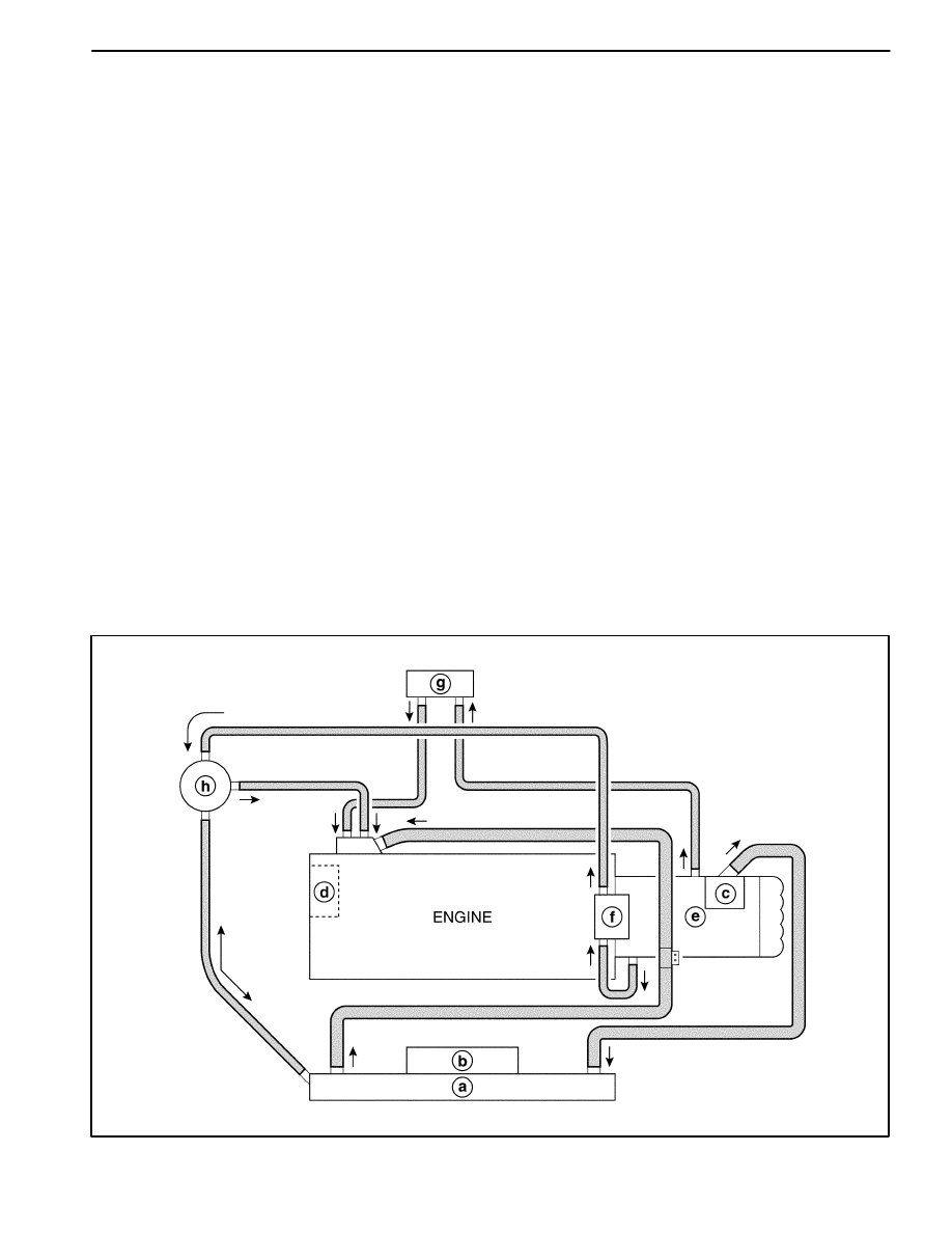
The cooling system includes a radiator(a) and cooling
fan(b), a thermostat and housing(c), a coolant pump(d),
a coolant pump drive belt and coolant hose. The timing
belt drives the coolant pump.

All components must function properly in order for the
cooling system to operate. The coolant pump draws the
coolant from the radiator. The coolant then circulates
through water jackets in the engine block and the cylin-
der head, distributor case(e), throttle body(f). When the
coolant reaches the operating temperature of the ther-
mostat, the thermostat opens. The coolant then goes
back to the radiator where it cools.

This system directs some coolant through the hoses to
the heater core(g). This provides for heating and de-
frosting. The surge tank(h) is connected to the radiator
and throttle body to recover the coolant displaced by ex-
pansion from the high temperatures. The surge tank
maintains the correct coolant level.

The cooling system for this vehicle has no radiator cap
and drain cock. The coolant is added to the cooling sys-

tem through the surge tank. To drain the cooling system,
disconnect the lower radiator hose and drain the cool-
ant.

RADIATOR

This vehicle has a lightweight tube-and-fin aluminum ra-
diator.

SURGE TANK

The surge tank is a transparent plastic reservoir, similar
to the windshield washer reservoir.

The surge tank is connected to the radiator and throttle
body by a hose. As the vehicle is driven, the engine cool-
ant heats and expands. The portion of the engine cool-
ant displaced by this expansion flows from the radiator
into the surge tank. The air trapped in the radiator is de-
gassed into the surge tank.

When the engine is stops, the engine coolant cools and
contracts. The displaced engine coolant is then drawn
back into the radiator. This keeps the radiator filled with
the coolant to the desired level at all times and increases
the cooling efficiency.

Maintain the coolant level between the MIN and the
MAX marks on the surge tank when the system is cold.

D102D001

ENGINE COOLING 1D – 3

COOLANT PUMP

The belt-driven centrifugal coolant pump consists of an
impeller, a drive shaft, and a belt pulley.

The impeller is supported by a completely sealed bear-
ing.

The coolant pump is serviced as an assembly and,
therefore, cannot be disassembled.

THERMOSTAT

A wax pellet-type thermostat controls the flow of the en-
gine coolant through the engine cooling system. The
thermostat(i) is mounted in the thermostat housing.

The thermostat stops the flow of the engine coolant from
the engine to the radiator in order to provide faster
warm-up, and to regulate the coolant temperature. The
thermostat remains closed while the engine coolant is
cold, preventing circulation of the engine coolant
through the radiator. At this point, the engine coolant is
allowed to circulate only throughout the heater core to
warm it quickly and evenly.

As the engine warms, the thermostat opens. This allows
the engine coolant to flow through the radiator, where
the heat is dissipated through the radiator. This opening
and closing of the thermostat permits enough engine
coolant to enter the radiator to keep the engine within
proper engine temperature operating limits.

The wax pellet in the thermostat is hermetically sealed in
a metal case(j). The wax element of the thermostat ex-
pands when it is heated and contracts when it is cooled.

As the vehicle is driven and the engine warms, the en-
gine coolant temperature increases. When the engine
coolant reaches a specified temperature, the wax pellet
element in the thermostat expands and exerts pressure
against the metal case, forcing the valve open. This al-
lows the engine coolant to flow through the engine cool-
ing system and cool the engine.

As the wax pellet cools, the contraction allows a spring
to close the valve.

The thermostat begins to open at 82

_

C (180

_

F) and is

fully open at 95

_

C (203

_

F). The thermostat closes at

80

_

C (176

_

F).

D102D002

ELECTRIC COOLING FAN

Caution: Keep hands, tools, and clothing away from
the engine cooling fans to help prevent personal in-
jury. This fan is electric and can turn ON whether or
not the engine is running.

Caution: If a fan blade is bent or damaged in any
way, no attempt should be made to repair or reuse
the damaged part. A bent or damaged fan assembly
should always be replaced with a new one.

The cooling fans are mounted behind the radiator in the
engine compartment. The electric cooling fans increase
the flow of air across the radiator fan and across the
condenser on air conditioner (A/C)-equipped vehicles.
This helps to speed cooling when the vehicle is at idle or
moving at low speeds.

D102D003

1D – 4 ENGINE COOLING

The main fan size is 320 mm (12.6 in.) in diameter with
seven blades(k) to aid the air flow through the radiator
and the condenser. An electric motor(l) attached to the
radiator support drives the fan.

A/C OFF or Non-A/C Model

D

The cooling fan is actuated by the electronic control
module (ECM) using a low speed cooling fan relay
and a high speed cooling fan relay. On A/C equipped
vehicles, a series/parallel cooling fan relay is also
used.

D

The ECM will turn the cooling fan on at low speed
when the coolant temperature reaches 93

_

C (199

_

F)

and high speed at 100

_

C (212

_

F).

D

The ECM will change the cooling fan from high speed
to low speed at 97

_

C (207

_

F) and turn the cooling

fans off at 90

_

C (194

_

F).

A/C ON

D

The ECM will only turn the cooling fan on at high
speed when the A/C system is on regardless of any
condition.

ENGINE COOLANT TEMPERATURE
SENSOR

The engine coolant temperature (ECT) sensor (n) uses
a thermistor to control the signal voltage to the engine
control module (ECM).

D102D004

COOLANT TEMPERATURE SENSOR

The coolant temperature sensor(m) controls the instru-
ment panel temperature indicator. The coolant tempera-
ture sensor is located on the distributor case with the
ECT sensor on an SOHC engine.

ENGINE COOLING 1D – 5

COMPONENT LOCATOR

COOLANT HOSE AND COMPONENTS

D12D4011

1 Radiator Coolant Return Hose
2 Upper Radiator Hose
3 Not Used
4 Radiator Assembly
5 Lower Radiator Hose
6 Throttle Body Assembly
7 Surge Tank hose
8 Surge Tank
9 Coolant Temperature Sensor

10 Engine Coolant Temperature Sensor

11 Surge Tank Return Hose

12 Water Inlet Cap
13 Heater Outlet Hose
14 Heater Inlet Hose
15 Distributor Case
16 Thermostat
17 Thermostat Housing
18 Throttle Body Inlet Hose
19 Throttle Body Outlet Hose
20 Hose Bracket


Content   ..  6  7  8  9   ..