Daewoo Korando. Manual - part 276


  Index      Daewoo     Daewoo Korando - service repair manual


Search            


Content   ..  274  275  276  277   ..


Daewoo Korando. Manual - part 276


MANUAL TRANSMISSION  5B-17

UNIT REPAIR

MAJOR UNIT

Preceding Work : Removal of the transmission

Removal of the transfer case

Disassembly Procedure

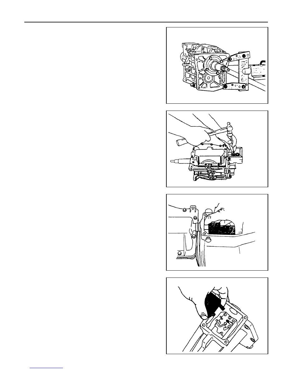
1. Install the removed transmission into a fixture.

2. Remove the drain plug and drain the oil. Using a 13 mm

wrench, remove the clamp bolt and position the offset lever
in the 3-4 position of neutral.

Notice

Removal of the offset lever in a position other than 3-4 of
neutral will be difficult.

3. Using a pin punch and a hammer, remove the roll pin to

remove the shift lever from the offset lever.

4. Using a 15 mm wrench, remove the 8 bolts from the extension

housing.

5. Separate the extension housing from the case and shift

cover.

Separate the offset lever from the shift.

Notice

Do not remove the offset lever while the extension housing
is still assembled to the case.

6. Remove the offset lever from the extension housing with

the detent ball and spring.

7. Remove the roll pin from either the offset lever or extension

housing.

5B-18  MANUAL TRANSMISSION

8. Remove the counter shaft thrust race and bearing.

9. Carefully remove the oiling funnel from the end of the

counter shaft.

10. Using a 10 mm wrench, remove the 10 bolts from the shift

cover.

Notice

For assembly, note the location of the two bolts.

11. Lift up the shift cover after sliding it toward the drain plug

about 3 cm. At this time remove sealer bond.

12. Using a needle nose pliers, remove the 5-R lever clip.

MANUAL TRANSMISSION  5B-19

13. Using a 21 mm wrench or a T-50 bit, remove the 5-R lever

pivot bolt.

Notice

Apply sealer bond to this bolt during assembly.

14. Using a 22 mm wrench, remove the back-up lamp switch

from the 5-R lever side.

Notice

Apply sealer to the threads.

15. Pull out the 5-R lever out of the transmission.

16. Using a snap ring pliers, remove the 5th synchronizer snap

ring from the end of the counter shaft.

17. Remove the 5th synchronizer assembly with its fork and

rail assembly from the counter shaft.

5B-20  MANUAL TRANSMISSION

18. Remove the slip yoke snap ring from the main shaft.

19. Remove the 5th speed drive gear snap ring from the main

shaft.

20. Make alignment marks on the case and input bearing

retainer and remove the 4 input shaft bearing retainer bolts,
using a 13 mm wrench.

Notice

Apply sealer on these bolts during assembly.

Remove the input bearing retainer with the bearing outer
race and shim.

21. Remove the input shaft from the case by rotating it until

the flat surface appears.

22. Remove the following parts from the input shaft.

l

4th speed gear blocking ring.

l

Main shaft thrust race and bearing.

l

Main shaft pilot bearing rollers (15 rollers).

Notice

Be careful not to dissipate the pilot bearing rollers.


Content   ..  274  275  276  277   ..