Daewoo Korando. Manual - part 261


  Index      Daewoo     Daewoo Korando - service repair manual


Search            


Content   ..  259  260  261  262   ..


Daewoo Korando. Manual - part 261


AUTOMATIC TRANSMISSION  5A-87

Transmission Case

To teardown the transmission case, proceed as follows:

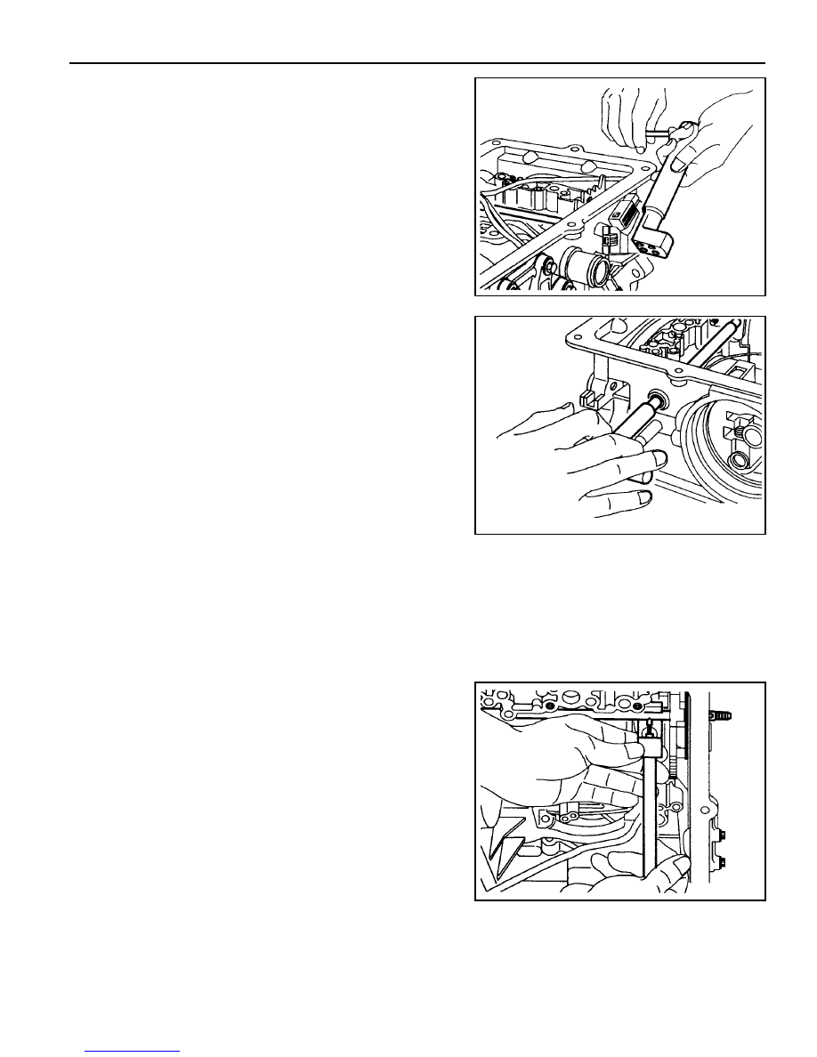
1. Remove the pin from the cross shaft inhibitor switch side

(4WD models) using tool No.0555-332942.

2. Remove the inhibitor switch from the case.

Remove the cross shaft seals with special tool No.0555-
331893.

3. Remove the circlip from the cross-shaft. Pull the shaft to

release the drive pin from the selector quadrant.

4. Using tool No. 0555-331897, press the pin from the cross-

shaft and withdraw the shaft from the case. Retrieve the
spring and pin

5. Remove the manual valve lever and the park rod.

6. Remove the 10 pin plug from the wiring loom bracket

adjacent to the inhibitor switch(RWD models),

7. Depress the tangs and withdraw the 10 pin connector from

the case. Remove the loom assembly.

5A-88  AUTOMATIC TRANSMISSION

8. Detach the No.7 solenoid wire from the front of the case.

9. Remove the parking pawl pivot pin and the pawl and spring

from the case.

10. Remove the shaft and the rear servo lever.

11. Remove the rear servo cover and piston assembly.

12. Remove the B1R circlip, valve and spring.

13. Remove both band adjustment shims.

14. Inspect the output shaft bushing in the case and replace if

necessary.

15. Inspect cooler line fittings and replace as necessary.

16. Inspect the case for damage.

17. To remove the park rod lever: Remove the circlip from the

inner end of the pivot shaft and tap the outer end of the
shaft until it moves free from the case, then using a wide
shallow tapered drift as a wedge, drive the pin out from
the inside of the case and remove the lever and spring.

Notice

Do not remove the park rod lever unless absolutely
necessary.

AUTOMATIC TRANSMISSION  5A-89

Forward Clutch Cylinder

To remove the forward clutch cylinder, refer to figure 8.4,
proceed as follows.

1. Place the assembly in a horizontal position.

2. Remove the thrust bearing and adjustment shims from the

input shaft.

3. Remove the circlip from the front of the clutch cylinder and

remove the input shaft.

4. Remove the overdrive shaft and the C1 clutch hub assembly

from the clutch cylinder.

5. Remove the C1 clutch plates from the cylinder.

6. Remove the circlip retaining the C3 clutch hub in the rear of

the clutch cylinder and remove the hub.

7. Remove the C2/C4 clutch hub assembly and remove the

thrust bearing from the C4 hub.

8. Remove the C2 clutch plates.

9. Invert the clutch cylinder and remove the C4 clutch sleeve,

clutch plates and the two wave washers. The 3-4 one way
clutch is located between the C2 and C4 clutch hubs, and
the hubs may be separated by rotating one hub clockwise
and withdrawing it from the other.

Figure 8.4 - Forward Clutch Cylinder Assembly

5A-90  AUTOMATIC TRANSMISSION

10. Remove the thrust block from the C4 clutch cylinder hub.

Notice

Make sure that the spring keeper is not caught in the circlip
groove, and that all the spring pressure is released, before
removing the tool.

11. Mount the clutch cylinder on tool No.0555-331899 with

the C2/C4 end uppermost and compress the piston return
spring. Remove the spring retaining circlip. Release the
tool and remove the circlip, keeper and spring.

12. Invert the clutch cylinder on the compressor tool and

remove the C1 clutch piston return spring in a similar
manner.

13. To remove the clutch pistons from the clutch cylinder, apply

air pressure to the apply ports in the bore of the cylinder.


Content   ..  259  260  261  262   ..