Daewoo Korando. Manual - part 250


  Index      Daewoo     Daewoo Korando - service repair manual


Search            


Content   ..  248  249  250  251   ..


Daewoo Korando. Manual - part 250


AUTOMATIC TRANSMISSION  5A-43

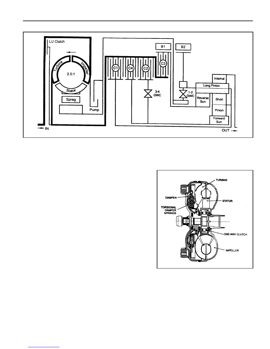
Figure 4.1 - Power Flow Diagram

TORQUE CONVERTER

The torque converter (refer figure 4.2) consists of a turbine,
stator pump, impeller and a lock-up damper and piston
assembly. As in conventional torque converters, the impeller is
attached to the converter cover, the turbine is splined to the
input shaft and the stator is mounted on the pump housing via
a one way clutch (sprag).

The addition of the damper and piston assembly enables the
torque converter to ‘lock-up’ under favourable conditions. Lock-
up is only permitted to occur in third and fourth gears under
specified throttle and road speed conditions.

Lock-up is achieved by applying hydraulic pressure to the
damper and piston assembly which couples the turbine to the
converter cover, locking-up the converter and eliminating
unwanted slippage. Whenever lock-up occurs, improved fuel

consumption is achieved. Torsional damper springs are
provided in the damper and piston assembly to absorb any
engine torque fluctuations during lock-up.

Figure 4.2 - Torque Converter Cross Section

5A-44  AUTOMATIC TRANSMISSION

CLUTCH PACKS

There are four clutch packs (refer to figure 4.3). All clutch packs are composed of multiple steel and friction plates.

C1 CLUTCH

When applied, this clutch pack allows the input shaft to drive the planet carrier.

This occurs in third and fourth gears.

C2 CLUTCH

When applied this clutch pack allows the input shaft to drive the forward sun gear via the 3-4 OWC.

This occurs in all forward gears.

C3 CLUTCH

When applied this clutch pack allows the input shaft to drive the reverse sun gear. This only occurs in

reverse gear.

C4 CLUTCH

When applied this clutch provides engine braking on overrun. This occurs in Manual 1, 2 and 3 and

also Drive 2 and Drive 3 to prevent objectionable free wheel coasting.

Figure 4.3 - Clutch Packs

AUTOMATIC TRANSMISSION  5A-45

BANDS

The transmission utilises two bands, the B1 band (sometimes known as the 24 band), and the B2 band (sometimes
known as the low-reverse band). Refer to figure 4.4.

The B1 band is a flexible band which is engaged by the front servo piston. B1 is activated in second and fourth gear.
When activated B1 prevents the reverse sun gear from rotating by holding the C3 clutch assembly stationary. In
second gear only the outer area of the apply piston is utilised. In fourth gear both areas are utilised for greater
clamping force.

The B2 band is a solid band which is engaged by the rear servo piston. B2 is activated in Park,

Reverse, Neutral and Manual 1. When activated B2 prevents the planet carrier assembly from rotating. In Manual 1
only the inner area of the apply piston is utilised. In Park, Reverse and Neutral, both areas are utilised for greater
clamping force.

Figure 4.4- Bands

ONE WAY CLUTCHES

The transmission uses two OWCs, the 1-2 OWC and the 34 OWC. (Note that a third OWC is located in the torque
converter, also known as a sprag.)

The 1-2 OWC is located between the planetary carrier assembly and the centre support. This allows the carrier to
rotate around the centre support in one direction only. The one way clutch is engaged only in Drive 1.

The 3-4 OWC is located between the C4 and the C2 clutch assemblies. This allows the C2 clutch to drive the forward
sun gear in first, second and third gears but unlocks in fourth gear and during overrun.

PLANETARY GEAR SET

The planetary gear set used in the transmission is a conventional six pinion Ravigneaux compound gear set.

5A-46  AUTOMATIC TRANSMISSION

PARKING MECHANISM

When Park is selected the manual lever extends the park rod rearwards to engage the parking pawl (refer to (figure
4.5). The pawl will engage the external teeth on the ring gear thus locking the output shaft to the transmission case.
When Park is not selected a return spring holds the parking pawl clear of the output shaft, preventing accidental
engagement of Park.

Figure 4.5 - Park Rod and Cross Shaft


Content   ..  248  249  250  251   ..