Daewoo Korando. Manual - part 246
AUTOMATIC TRANSMISSION 5A-27
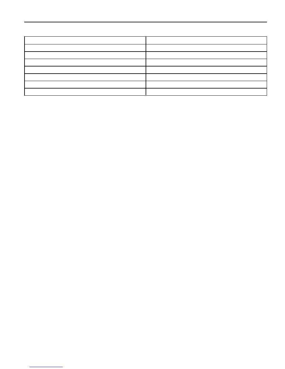
Shift Lever Position
Manual 1
Manual 2
Manual 3
Drive
Netural
Reverse
Park
Resistance (OHMS)
1k - 1.4k
1.8k - 2.2k
3k - 3.4k
4.5k - 4.9k
6.8k - 7.2k
10.8k - 11.2k
18.6k - 19k
Table 3.3 - Readings for Resistance/Shift Lever Positions
Diagnostics Inputs
The diagnostics control input or K-line is used to initiate the outputting of diagnostics data from the TCU to a diagnostic
test instrument. This input may also be used to clear the stored fault history data from the TCU’s
retentive memory. Connection to the diagnostics input of the TCU is via a connector included in the vehicle’s wiring
harness or computer interface. Refer to the vehicle manufacturer’s manual for the location of the self test
connectors.
Battery Voltage Monitoring Input
The battery voltage monitoring input connects to the positive side of the battery. The signal is taken from the
main supply to the TCU.
If operating conditions are such that the battery voltage at the TCU falls below 11.3V the transmission will adopt a ‘low
voltage’ mode of operating in which shifts into first gear are inhibited. All other shifts are allowed but may not occur
because of the reduced voltage. This condition normally occurs only when the battery is in poor condition.
When system voltage recovers, the TCU will resume normal operation after a 3 second delay period.
TCU Outputs
The outputs from the TCU are supplied to the components described below:
Solenoids
The TCU controls seven solenoids. Solenoids 1 to 6 (S1 to S6) are mounted in the valve body, while Solenoid 7 (S7)
is mounted in the pump cover. The normal state (OPEN/CLOSED) and the functions associated with the solenoids
are detailed in table 3.4. Table 3.5 details the S1 and S2 logic for static gear states. The logic during gear changes for
S1 to S4 and S7 is detailed in table 3.6.