Daewoo Korando. Manual - part 186


  Index      Daewoo     Daewoo Korando - service repair manual


Search            


Content   ..  184  185  186  187   ..


Daewoo Korando. Manual - part 186


1F3-28  OM600 ENGINE CONTROLS

Tools Required

001 589 65 09 00  Socket Wrench Insert

000 589 00 68 00  Cleaning Set

Repair Procedure

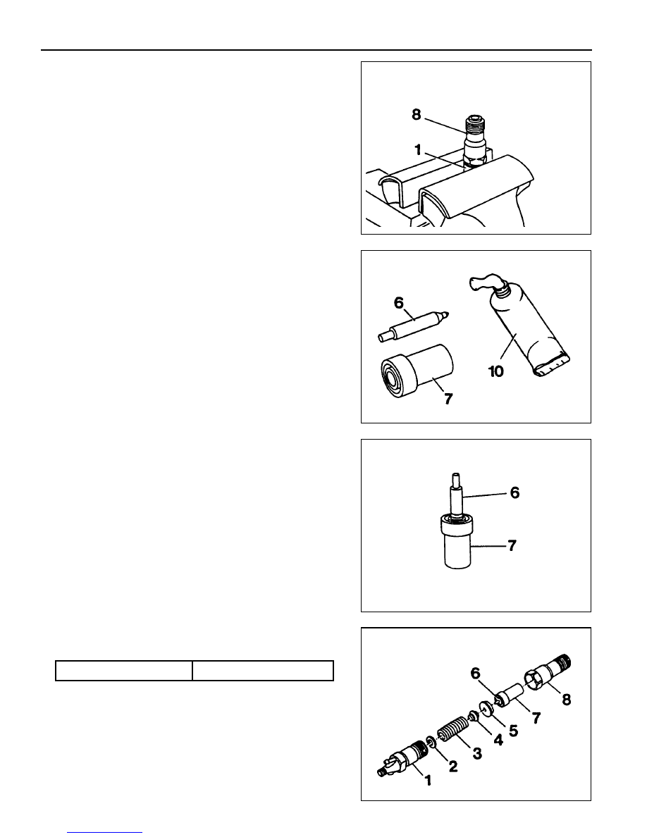
1. Clamp the nozzle holder (1) in a vice and remove the nozzle

tensioning nut (8).

Notice

Use protective jaws for clamping.

2. Disassemble the fuel injection nozzle.

Socket Wrench Insert 001 589 65 09 00

3. Clean the nozzle needle (6) and nozzle body (7) with an

abradant.

4. Clean the nozzle seat with cleaning cutter.

Cleaning Set 000 589 00 68 00

5. Immerse nozzle needle (6) and nozzle body (7) in filtered

diesel fuel. When the nozzle body is held vertical, the weight
of the nozzle needle must cause it to slide down toward the
nozzle needle seat.

6. Assemble the injection nozzle  so that the tip of the thrust

(4) pin is facing toward the nozzle holder.

Tightening Torque

80 Nm

Notice

Nozzle needle (6) and nozzle body (7) should always be
replaced as a pair.

OM600 ENGINE CONTROLS  1F3-29

7. Check the fuel injection nozzle and adjust opening pressure

if necessary.

Opening pressure adjustment

Disassemble the fuel injection nozzle and replace the steel
washer (2).

Notice

Each 0.05mm thickness of the washer results in a pressure
difference of approx. 3bar.

1F3-30  OM600 ENGINE CONTROLS

REMOVAL AND INSTALLATION OF INJECTION TIMING DEVICE

Preceding Work : Removal of vacuum pump

1 Cylinder Head Cover
2 Bolt ............................................................ 10Nm
3 Gasket ................................................... Replace
4 Fuel Injection Pump
5 Seal ....................................................... Replace
6 Screw Plug ................................................. 30Nm
7 Oil Pan
8 Locking Pin
9 Injection Timing Device

10 Washer

11 Bolt (Left-Hand Thread) ............................. 46Nm

12 Camshaft Sprocket
13 Washer
14 12-Sided Stretch Bolt ............ Check, 25Nm + 90°
15 Timing Chain
16 Seal
17 Chain Tensioner ......................................... 80Nm

OM600 ENGINE CONTROLS  1F3-31

Tools Required

601 589 00 08 00 Flange

601 589 05 21 00 Locking Screw

116 589 20 33 00 Sliding Hammer

116 589 02 34 00 Threaded Bolt

667 589 04 63 00 Retaining Plate

Removal & Installation Procedure

1. Remove the bolts (2) and then remove the cylinder head

cover (1) and gasket (3).

Installation Notice

Tightening Torque

10 Nm

Notice

Replace the gasket.

Rotate the engine 1 revolution by hand and check TDC
marking of the crankshaft and camshaft.

2. Loosen the camshaft sprocket bolt (14).

Notice

Do not remove the bolt.

Installation Notice

Notice

If max. length of bolt exceeds 53.6mm, replace it.

Tightening  Torque

25Nm + 90°

3. Loosen the bolt (11) (left-hand thread).

Notice

Do not remove the bolt.


Content   ..  184  185  186  187   ..