Daewoo Korando. Manual - part 165


  Index      Daewoo     Daewoo Korando - service repair manual


Search            


Content   ..  163  164  165  166   ..


Daewoo Korando. Manual - part 165


1F2-24  M161 ENGINE CONTROLS
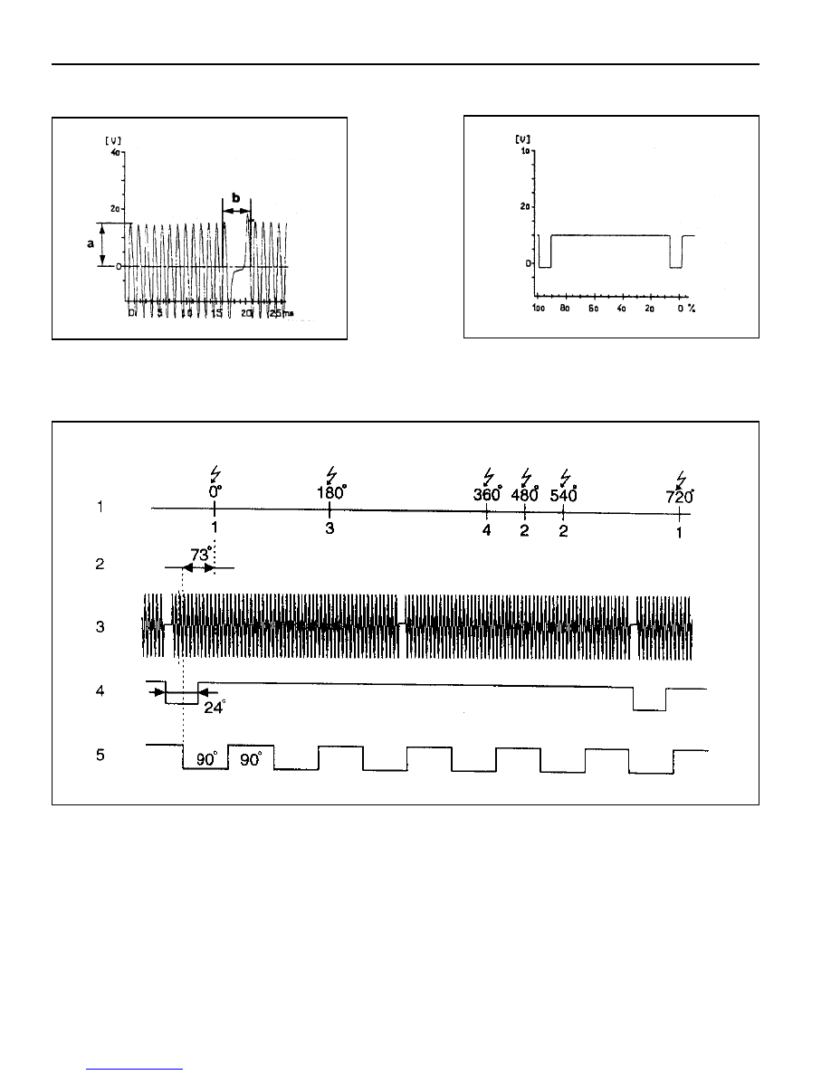
Reference Figures

Figure 5. Crankshaft Position Sensor Signal
a

Voltage

b

Identifying the No.1 - 2 Missing Teeth

Figure 6. Camshaft Position Sensor Signal

Figure 7. Signal Function
1

Crank Angle

2

Cylinder

3

Crankshaft Position Sensor Signal

4

Camshaft Position Sensor Signal

5

RPM Signal

M161 ENGINE CONTROLS  1F2-25

IDLING CONTROL AND ELECTRONIC PEDAL SYSTEM TEST

Þ 

2.1

·


Ignition:ON

50

51

2.25 - 2.75 V

·

·

·

·

·

 Pedal valve

sensor:

- Power

supply


(potentiometer 2)

·

 Cable

·

 ECU

Failure

code

Item

Þ 

1.0

Checking method

·


Ignition:ON

·

 Position of

accelerator pedal:

- Closed throttle

position

- Full throttle with

kick down

Test

step

Requirement

Specified

value

Possible cause

31

47

0.2 - 0.5 V

·

·

·

·

·

 Pedal valve

sensor:

- Signal


(potentiometer 1)

160,

161,

164,

167,

4.3 - 4.8 V

·


Þ 

1.1

·

 Cable

·

 Pedal valve sensor

Þ 

1.1

·


Ignition:ON

31

32

4.75 - 5.25 V

·

·

·

·

·

 Pedal valve

sensor:

- Power

supply


(potentiometer 1)

·

 Cable

·

 ECU

Þ 

2.0

·


Ignition:ON

·

 Position of

accelerator pedal:

- Closed throttle

position

- Full throttle with

kick down

50

48

0.1 - 0.4 V

·

·

·

·

·

 Pedal valve

sensor:

- Signal


(potentiometer 2)

162,

163,

164,

167,

2.1 - 2.5 V

·


 Þ 

2.1

·

 Cable

·

 Pedal valve sensor

Þ 

3.0

·


Engine:in idling

84

87

0.3 - 0.9 V

·

·

·

·

·

 Throttle

valve

actuator:

- Signal

Throttle valve

 potentiometer

1

104,

105,

108,

109,

116,

119,

185,

4.0 - 4.6 V

·


Þ 

3.1

·

 Cable

·

 E-GAS actuator

·

 Position of

accelerator pedal:

- Closed throttle

position

- Full throttle with

kick down

1F2-26  M161 ENGINE CONTROLS

Failure

code

Item

Checking method

Test

step

Requirement

Specified

value

Possible cause

Þ 

3.1

·


Ignition:ON

84

112

4.75 - 5.25 V

·

·

·

·

·

 Throttle

valve

actuator:

- Power

supply

·

 Cable

·

 ECU

Þ 

4.0

·


Ignition:ON

68

67

0.8 - 2.3 V

The value will

be changed in

1.0 - 2.5V.

·

·

·

·

·

 Throttle

valve

actuator:

- Signal

Throttle valve

actuator

motor

voltage

supply

104,

105,

108,

109,

116,

119,

185,

·

 ECU

·

 Cable

·

 E-GAS actuator

·

 Engine:in idling

- Coolant

temperature:

  > 70 

°

C

84

85

4.0 - 4.6 V


Throttle valve

potentiometer

2

0.3 - 0.9 V

·

 Position of

accelerator pedal:

- Closed throttle

position

- Full throttle with

kick down

Throttle

valve

potentiometer

1+2

·


Ignition:OFF

< 10 

W

Throttle valve

actuator

motor

resistance

68

67

M161 ENGINE CONTROLS  1F2-27

AIR CONDITIONER CONTROL SYSTEM TEST

Þ 

2.0

·


Engine:In idling

·

 Air conditioner

switch:ON/OFF

Air conditioner

switch:OFF

Air conditioner

switch:ON

Coolant temperature:

above 150 

°

C

10

35

11 - 14 V

11 - 14 V

< 1 V

·

·

·

·

·

 Condenser

fan(HI)

control:

Failure

code

Item

Þ 

1.0

Checking method

·


Engine:In idling

·

 Air conditioner

switch:ON/OFF

Air conditioner

switch:OFF

Air conditioner

switch:ON

Test

step

Requirement

Specified

value

10

44

< 1 V

·

·

·

·

·

 Air

conditioner

signal:

- Input signal

(input signal

from thermo

amplifier)

44,

45,

11 - 14 V

·


Þ 

5.1

·

 Cable

·

 Thermo amp

·

 Auto amp

·

 Dual pressure

switch

·

 Air conditioner

control panel

Þ 

1.1

·


Engine:In idling

·

 Air conditioner

switch:ON/OFF

Air conditioner

switch:OFF

Air conditioner

switch:ON

10

27

< 1 V

·

·

·

·

·

 Air

conditioner

compressor:

- Output

signal

11 - 14 V


Content   ..  163  164  165  166   ..