DAF CF65, CF75, CF85 Series . Manual - part 953


  Index      DAF     DAF CF65, CF75, CF85 Series - service repair manual


Search            


Content   ..  951  952  953  954   ..


DAF CF65, CF75, CF85 Series . Manual - part 953


©

 200423

3-5

Inspection and adjustment

STEERING GEAR, GENERAL

ΧΦ65/75/85 series

7

2

Items requiring special attention when 
connecting the test case
1.

Clean the delivery line connection that is 

going to be disconnected.

2.

Check the steering box attachment.

3.

Check the hydraulic central position.

4.

Place proper turning plates under the 

vehicle's steerable wheels.

Block the vehicle so that it cannot 

slide off the jack or the turning 

plates.

5.

With an EMAS-controlled trailing axle 

remove the fuses from the EMAS system.

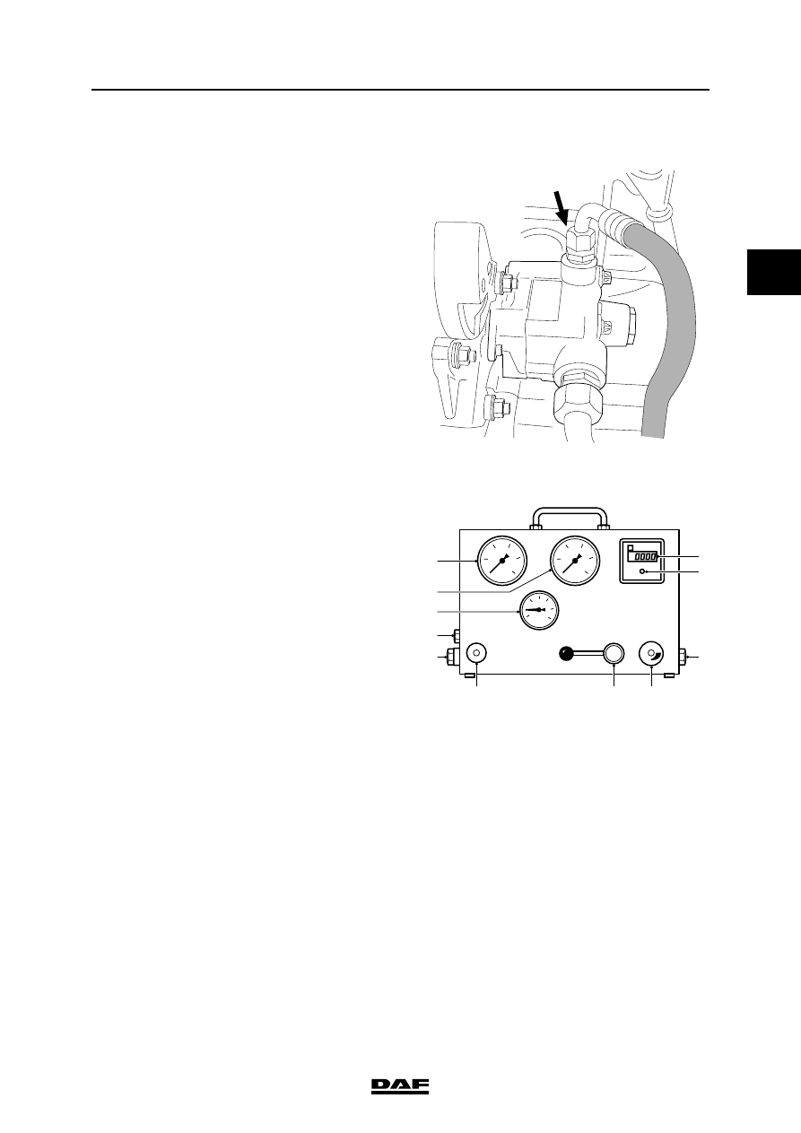
Connecting the test case
1.

Check whether the non-return valve (5) of 

the 'Servotest 550' is completely closed, the 

cock (4) has been fully opened and the 

pressure adjusting device (6) of the 

pressure-limiting valve is set in accordance 

with the maximum system pressure.

Only use couplings and lines which 

are suited to the maximum system 

pressure.

S7 00 585

}

50

100

150

200

250

5

10

15

20

25

  9

7
8

2

4

6

5

10
11

  1
  3

S7 00 020

}

STEERING GEAR, GENERAL

3-6

©

 200423

Inspection and adjustment

2

ΧΦ65/75/85 series

7

2.

Connect the test case to the delivery line. 

Make sure that as little steering oil as 

possible runs off. Collect the steering oil 

leaking out of the system.

Connect the hose from the "Eingang" 

connection of the test case to the part of the 

line coming from the main steering pump.

Connect the hose from the "Ausgang" 

connection of the test case to the part of the 

line going to the steering box.

Note:

If internal leakage needs to be measured in the 

steering box on an EMAS-controlled trailing axle, 

the test case should be connected between the 

EMAS fluid flow control valve and the steering 

box.

3.

Place the hose coming from the "Tank" 

connection into the reservoir. Attach this line 

to the reservoir and make sure that the end 

of the line stays below the oil surface (to 

prevent the forming of foam).

4.

Check the steering oil level and top up as 

necessary.

5.

Start the engine and keep an eye on the 

steering oil level.

Bringing the steering oil up to the test 
temperature
1.

Bleed the system by running the engine at 

idling speed for 2 minutes. Check the 

steering oil level at regular intervals, and top 

up as necessary. Do not touch the steering 

wheel during these 2 minutes.

2.

Run the engine at idling speed.

3.

Slowly close the cock (4), until the pressure 

gauge (10) reads a pressure of 50 bar.

4.

Wait until the thermometer (11) reads a 

value of 50

C.

5.

Now open the cock (4) completely.

S7 00 174

50

100

150

200

250

5

10

15

20

25

  9

7
8

2

4

6

5

10
11

  1
  3

S7 00 020

©

 200423

3-7

Inspection and adjustment

STEERING GEAR, GENERAL

ΧΦ65/75/85 series

7

2

Inspection of steering gear using the 

test case

Note:

-

During the measurements, the steering oil 

temperature should be checked regularly 

and, if required, the oil should be warmed as 

specified.

-

If during the measurements a deviating value 

is found, the cause of this deviation should 

be traced and rectified first, before 

continuing with the next measurement.

Measuring the circulation pressure
1.

Run the engine at idling speed.

2.

Open the cock (4) completely.

3.

The circulation pressure is indicated by the 

pressure gauge (9). Compare the reading 

with the maximum value allowed. See 

'Technical data'.

Inspection of front axle bearings
1.

Run the engine at idling speed.

2.

Check whether the cock (4) is fully opened.

3.

Turn the steering gear carefully from the 

central position to both maximum wheel 

deflections.

4.

Check whether the necessary pressure rises 

evenly.

Testing the maximum system pressure
1.

Run the engine at idling speed.

2.

Activate the steering gear and fit a 15-mm 

filler piece, special tool (DAF no. 0535996), 

between the adjusting bolt and the axle stop.

Be careful when fitting the 15-mm 

filler piece between the adjusting 

bolt and the axle stop, because there 

is a danger of limbs getting trapped. 

50

100

150

200

250

5

10

15

20

25

  9

7
8

2

4

6

5

10
11

  1
  3

S7 00 020

S7 00 598

}

STEERING GEAR, GENERAL

3-8

©

 200423

Inspection and adjustment

2

ΧΦ65/75/85 series

7

3.

Fit a torque wrench with a dial to the steering 

wheel nut and tighten the nut to a tightening 

torque of 45 Nm on the torque wrench.

4.

Read the pressure given by the gauge (10) 

(hold maximum pressure for no longer than 

5 seconds) and compare the measured 

value with the value specified, see 'Technical 

data'.

5.

Repeat the measurement using the 15-mm 

filler piece at the other side of the front axle.

Testing the final limiting pressure
1.

Turn the steering gear to maximum lock.

2.

Set the engine speed to 1200 - 1400 rpm.

3.

Fit a torque wrench with a dial to the steering 

wheel nut and tighten the nut to a tightening 

torque of 45 Nm on the torque wrench.

4.

The pressure gauge (10) will indicate the 

final limiting pressure.

5.

Compare the reading with the specified 

value, see 'Technical data'.

6.

Carry out the measurement at the other side 

of the axle as well.

Testing the maximum pump pressure
1.

Check whether the pressure-limiting valve 

(6) is set at the correct pressure.

2.

While the engine is at idling speed, slowly 

close the cock (4) until the maximum 

pressure is achieved at gauge (10). This 

maximum pressure should be maintained for 

5 seconds at the most. Otherwise the 

internal pump components will become too 

hot. This would result in premature wearing 

of the pump.

If the pressure-limiting valve (6) is set lower 

than the system pressure, the maximum 

system pressure will not be reached.

45Nm

45Nm

S7 00 565

50

100

150

200

250

5

10

15

20

25

  9

7
8

2

4

6

5

10
11

  1
  3

S7 00 020

45Nm

45Nm

S7 00 565

50

100

150

200

250

5

10

15

20

25

  9

7
8

2

4

6

5

10
11

  1
  3

S7 00 020


Content   ..  951  952  953  954   ..