DAF CF65, CF75, CF85 Series . Manual - part 846
11
35
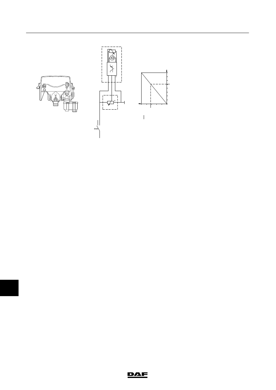
HEADLAMP
H
EIGHT
ADJUSTMENT
Operation
Parking/marker
lights
position
A
v
oltage
is
applied
to
c
onnection
2
o
f
s
witch
C622
(light
switch)
through
fuse
E084,
wire
1
101.
If
a
c
onnection
is
made
to
switch
C622
(contacts
2
and
1),
a
voltage
is
applied
to
contact
8
5
o
f
relay
G000
(rear
light/width
marker
light
relay)
via
w
ire
2100.
Once
the
relay
is
a
ctivated,
a
c
onnection
is
made
between
points
3
0
and
87.
As
a
result,
a
voltage
is
applied
through
relay
G
000
(contacts
30
-
87),
w
ire
2101,
fuse
E1
17
and
wire
2630
to
connection
point
A
o
f
s
witch
C764
(headlamp
height
adjustment
potentiometer).
The
L
ED
in
the
s
witch
w
ill
now
illuminate.
Dipped
b
eam
position
When
a
c
onnection
is
made
between
contacts
2
and
4
through
switch
C622,
a
v
oltage
is
applied
to
c
onnection
point
85
of
relay
G
000
through
fuse
E084,
wire
1
101,
switch
C622,
wire
21
10,
via
D
609
(light
switch
diode).
T
here
is
also
a
v
oltage
on
both
B
129
(left
headlamp
height
adjustment
motor),
c
onnection
point
1,
and
on
B130
(right
headlamp
height
adjustment
motor),
c
onnection
point
1
and
connection
point
3
o
f
C
764
(headlamp
height
adjustment
potentiometer).
Depending
upon
the
position
o
f
C
764
(headlamp
height
adjustment
potentiometer),
the
m
otor
in
the
headlamp
w
ill
be
activated.
The
headlamp
height
adjustment
motor
remains
activated
until
there
is
a
n
e
lectrical
equilibrium.
T
his
equilibrium
refers
to
the
v
oltage
dif
ference
that
exists
between
wires
21
10
and
4953
of
C764,
B129
and
B130.
The
v
oltage
dif
ference
should
b
e
the
same
for
a
ll
three
c
omponents.
24
5.2
6
20
40
60
65
80
100
8
[mm]
[%]
U
G
U
B
C764
C764
G
G
+
+
C622
B129 / B130
K100380
200332
ᓻ
3-142
5
CHANGES IN THE ELECTRICAL SYSTEM
Changes in the electrical system from chassis number 0E608863
CF65/75/85 series