DAF CF65, CF75, CF85 Series . Manual - part 834
11
20
1358030/25
EL001126
54
55
56
57
58
59
60
61
62
63
64
65
66
67
68
69
70
71
72
73
74
75
76
77
78
79
80
81
82
83
84
85
86
87
88
89
90
91
92
93
94
95
96
97
98
99
100
1
01
102
103
104
105
106
2630
2630
2630
2630
2630
2630
2630
2630
2630
2630
2630
2630
2630
2630
2630
2630
2630
2630
2630
2630
2630
2630
2630
2630
2630
2630
2630
2630
2630
2630
2630
2630
2630
2630
2630
2630
2630
2630
D929
1010
1000
1010
1000
9
558
20
554
7
597
A2/
598
B525
C725
A
B
C763
A
B
C858
1
10
C727
A
B
C840
A
B
C750
A
B
C751
A
B
C764
A
B
5
3
9
2
564
2
565
7
C814
10
6
2
7
C716
10
6
2
7
C813
10
6
2
7
623
10
554
4
568
21
568
18
558
21
554
12
597
12
623
9
564
6
565
200332
ᓻ
3-94
5
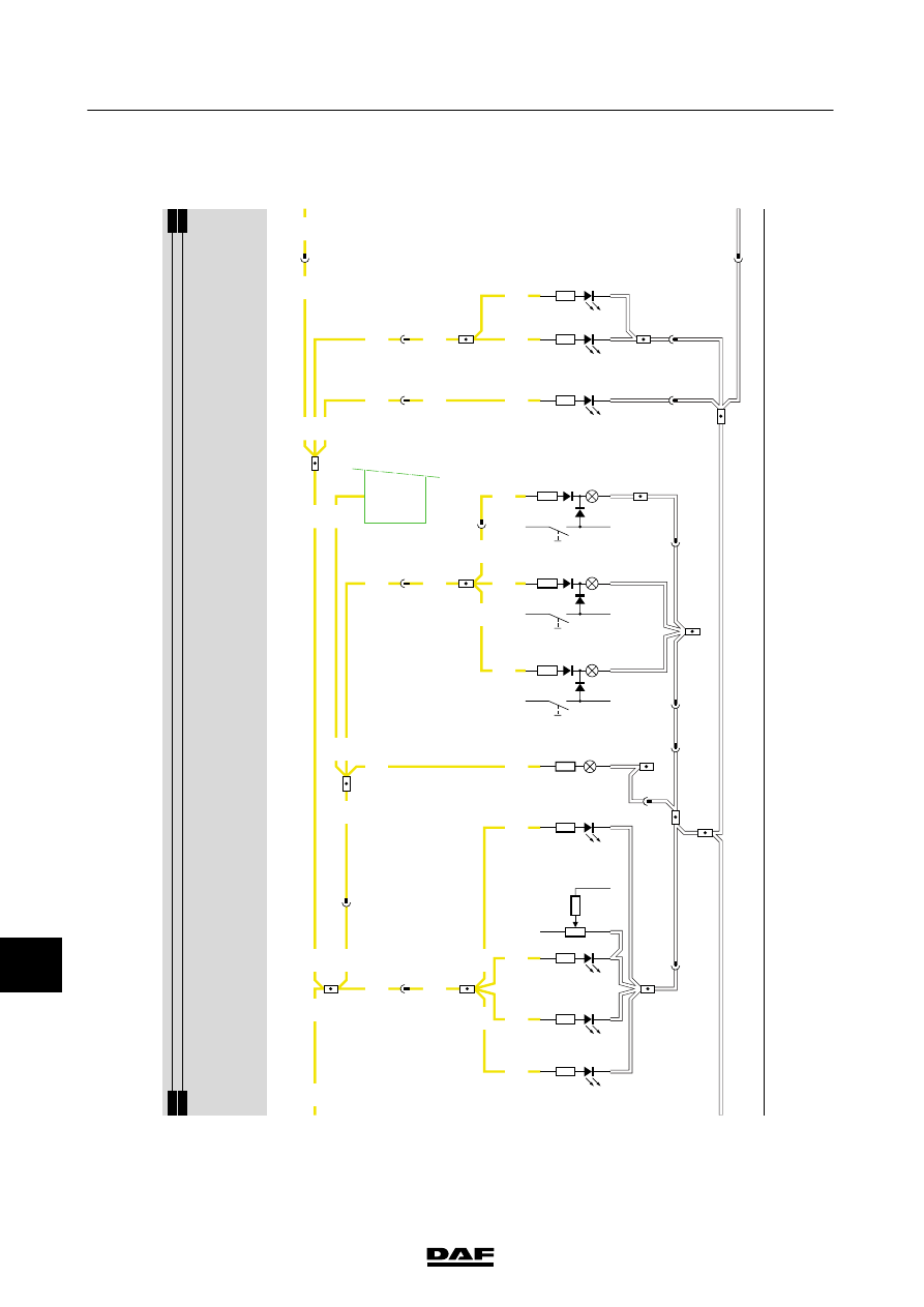
CHANGES IN THE ELECTRICAL SYSTEM
Changes in the electrical system from chassis number 0E608863
CF65/75/85 series