DAF CF65, CF75, CF85 Series . Manual - part 819
11
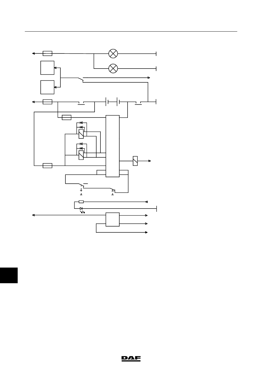
MAIN
SWITCH
FOR
PETREG
If
the
v
ehicle
has
an
Allison
gearbox
and
the
system
must
meet
specific
safety
requirements,
wire
no.
1009
(Allison
power
supply)
should
b
e
c
onnected
to
c
onnection
88a
of
relay
G
367.
Basic
c
ode
number
Description
A500
Batteries
A513
Integrated
voltage
regulator
generator
B525
T
a
chograph
C010
Position
of
cab
lamp
o
n
driver
’ss
id
e
C01
1
Position
of
co-driver
’ss
id
e
cab
lamp
C
8
5
3
S
w
it
c
h
fo
rm
a
ins
w
it
c
hi
n
cab
C
8
5
4
S
w
it
c
h
fo
rm
a
ins
w
it
c
ho
n
chassis
D826
Electronic
unit
for
VLG
current
limiter
D900
CF
65/75/85
VIC
electronic
unit
G368
Relay
,
main
switch
earth
D924
Electronic
unit
for
main
switch
E045
Fuse,
interior
lighting
E1
17
Fuse,
s
earch
light
E153
Engine
stop
main
switch
fuse
for
m
ain
s
witch
E286
High
output
fuse
E330
Fuse,
‘sens
’wire
main
switch
G367
Relay
,
power
supply
m
ain
switch
G425
Relay
,
main
switch
200332
ᓻ
3-34
5
CHANGES IN THE ELECTRICAL SYSTEM
Changes in the electrical system from chassis number 0E608863
CF65/75/85 series
E501326
30
87
87A
G368
1
2
1
2
C010
C011
1107
1000
1000
1167
1
2
+
+
-
-
1
2
5
86
85
85B
86
86
85B
85A
88
88A
88
88A
1
1
0
1
2
2
2
0
7
A
B
E286
1
2
E045
G367
A500
E153
1
2
E330
4177
C854
C4
C5
A7
A2
C1
C2
A1
A3
A4
A5
2630
1234
1234
4179
9306
1123
1
4
3
9001
1009
4176
4178
E117
1010
1010
A5
B525
9303
A1
B525
15
A513
E1
D900
C853
1167
4175
4174
3173
G425
G367
85A
G368
G425
D924
D826