DAF CF65, CF75, CF85 Series . Manual - part 631
11
30
1358030/30-34
EL001535
160
161
162
163
164
165
166
167
168
169
170
171
172
173
174
175
176
177
178
179
180
181
182
183
184
185
186
187
188
189
190
191
192
193
194
195
196
197
198
199
200
201
202
2
03
204
205
206
207
208
209
210
211
212
5687
5687
5687
5688
5688
6036
6036
5689
5689
5690
5690
5656
5657
5656
5657
5658
5659
5658
5659
5692
5694
5694
5695
5660
5661
5692
5694
5693
5693
5694
5691
5695
5691
5695
5695
5661
5660
5695
5660
5661
5660
5661
5682
5682
5683
5683
5684
5684
5685
5685
5686
5686
5687
5687
D929
1010
1000
1010
1000
A032
A
H
J
K
1
648
2
648
N
F601
SR
3
648
4
648
N
F602
PN
2
649
4
649
5
649
5
648
6
648
3
649
1
649
N
F670
ML
U
F669
DC
B354
GH
B353
FE
6
607
7
607
8
607
9
607
10
607
D866
S32
S4
S27
S1
S17
T16
T32
T14
T30
T23
T19
T24
T28
T25
T15
T31
S9
S10
S15
S14
S16
D867
E
M
L
SRP
A071
1
2
607
11
200520
3-92
5
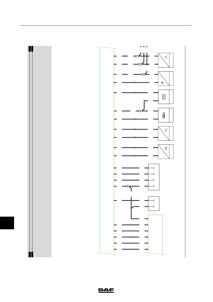
CHANGES IN THE ELECTRICAL SYSTEM
Changes in the electrical system from
chassis number 0E646818
CF65/75/85 Serie ≥0E621376