DAF CF65, CF75, CF85 Series . Manual - part 577
10
34B
1358030/26
EL001353
54
55
56
57
58
59
60
61
62
63
64
65
66
67
68
69
70
71
72
73
74
75
76
77
78
79
80
81
82
83
84
85
86
87
88
89
90
91
92
93
94
95
96
97
98
99
100
101
102
103
104
105
106
4741
4741
4742
4742
4740
4740
4741
4742
4740
4751
4740
4751
4740
3502
3502
3502
4755
4754
4754
4755
4732
4732
4732
9009
9009
9009
4739
4739
4753
1221
4753
4753
4736
4739
4753
1221
4736
4736
4727
4727
9009
9009
9009
9009
9009
9009
9009
9009
9009
9009
9009
9009
1221
5
627
6
627
12
929
4
627
6
929
7
929
5
929
4
B253
3
1
2
6
635
5
635
9
627
8
627
4
B166
3
1
1
635
1010
1000
1010
1000
D929
9
555
8
861
B525
B6/
599
4
B254
3
1
7
A021
16
861
11
627
10
627
2
627
11
929
2
635
F612
1
L
2
F613
1
L
2
4
635
7
627
12
627
4
929
3
929
8
929
1
929
F614
1
L
2
P
U
F615
3
2
1
D802
11/
340
15/
340
31/
340
13/
340
22/
340
30/
340
12/
340
2/
340
4/
340
27/
340
19/
340
16/
340
25/
340
8/
340
26/
340
5/
340
6/
340
!
200404
2-148
5
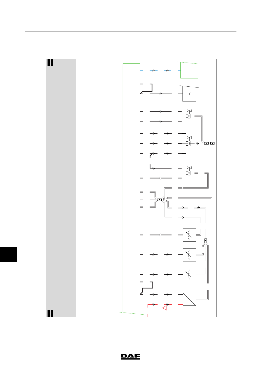
ELECTRICAL SYSTEM
Electrical system
CF65/75/85 series ≥0E621376