DAF CF65, CF75, CF85 Series . Manual - part 551
10
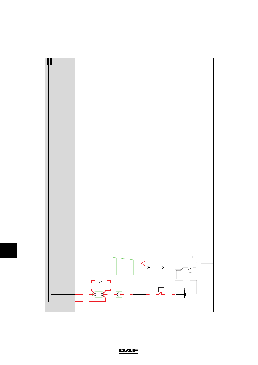
1358030/26
EL001298
1
54
55
56
57
58
59
60
61
62
63
64
65
66
67
68
69
70
71
72
73
74
75
76
77
78
79
80
81
82
83
84
85
86
87
88
89
90
91
92
93
94
95
96
97
98
99
100
101
102
103
104
105
106
1000
1008
1008
9001
9307
9307
9307
1010
1000
1000
1010
1000
A500
1/416
1/417
E286
125A
2
1
!
1
638
20
555
30
87
G015
B525
A5/
598
D929
1010
1000
1000
1010
B010
30
2
C694
BD
+
G
200404
2-44
5
ELECTRICAL SYSTEM
Electrical system
CF65/75/85 series ≥0E621376