DAF CF65, CF75, CF85 Series . Manual - part 471


  Index      DAF     DAF CF65, CF75, CF85 Series - service repair manual


Search            


Content   ..  469  470  471  472   ..


DAF CF65, CF75, CF85 Series . Manual - part 471


©

 200324

4-11

Removal and installation

XE ENGINE FUEL SYSTEM

CF65/75/85 series

4

8

6.

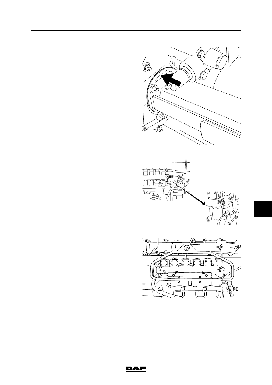
Remove the timing gear seal by tapping it out 

of the timing gear case in the driving 

direction.

7.

Remove the electrical connections from the 

pump units.

8.

Remove the fuel pipes from the pump 

housing.

9.

Remove the pressure relief valve from the 

pump housing.

10. Let the fuel leak from the pump housing.

11. Remove the fuel pipes from the fuel lift pump.

12. Remove the fuel injection pipes and plug the 

pump units and injectors so that no dirt can 

enter the system.

13. Remove the connector from the fuel 

temperature sensor (1) (if fitted on the pump 

housing).

14. Remove the camshaft position sensor (2).

}

Due to the weight of the pump 

housing, use the special tool.

15. Fit the lifting gear (DAF no. 1329499) to the 

pump housing and tighten the bolts (A).

16. Remove the attachment bolts of the pump 

housing and lift the pump housing off the 

dowel pins on the engine block using the 

lifting gear.

M200728

i 400529

2

1

i400601

A

A

XE ENGINE FUEL SYSTEM

4-12

©

 200324

Removal and installation

8

CF65/75/85 series

4

Installing the pump housing
1.

Fit two new lubricating oil connection sealing 

rings.

2.

Fit the pump housing using the lifting gear 

(DAF no. 1329499). Tighten the attachment 

bolts to the specified torque. See "Technical 

data".

3.

Fit the camshaft position sensor.

4.

Fit the fuel temperature sensor connector.

5.

Fit the electrical connections onto the pump 

units.

6.

Fit the injection pipes.

7.

Connect the fuel pipes of the fuel lift pump.

8.

Fit the pressure relief valve onto the pump 

housing.

9.

Fit the fuel pipes to the pump housing.

10. Fit a dry new timing case seal (6) using the 

special tool (DAF no. 1329318).

11. Check whether cylinder 1 is at top dead 

centre (TDC on the flywheel, cylinder 6 in 

overlap position).

4

6

7

M200841

©

 200324

4-13

Removal and installation

XE ENGINE FUEL SYSTEM

CF65/75/85 series

4

8

12. Fit the pump housing camshaft gear (4) in 

such a position that the idler gear (3) can be 

installed in accordance with the marks.

13. Fit the attachment bolts of the pump housing 

camshaft gear (4) and idler gear (3) and 

tighten to the specified torque. See 

"Technical data".

14. Fit the timing cover.

15. Bleed the fuel system. See "Inspection and 

adjustment".

M201281

2

1

3

4

XE ENGINE FUEL SYSTEM

4-14

©

 200324

Removal and installation

8

CF65/75/85 series

4

4.7 REMOVAL AND INSTALLATION, FUEL PIPES

Removal, fuel pipes
1.

Disconnect the earth lead from the battery 

terminal.

2.

Disconnect the appropriate fuel pipe and 

collect the escaping fuel.

3.

If the pipe is damaged in any way, it should 

be replaced.

}

Leaks from fuel pipes must be 

remedied as soon as possible to 

reduce fire risk.

Installation, fuel pipes
1.

Always use new copper sealing rings during 

fitting.

2.

Tighten union nuts and banjo bolts to the 

specified torque. See "Technical data".

Note:

In the event of a leakage from a pipe coupling, do 

not overtighten the union nut. First check whether 

the leak is at the connection point between the 

pipe and coupling or at the connection point 

between coupling and the component housing.

If the leakage has not stopped after the union nut 

has been tightened, it will be necessary to take 

the coupling apart.

Check the parts for deposits and/or damage.

Pipes may chafe if they touch each other or other 

parts of the vehicle.

Pipes showing evidence of wear must be 

replaced without delay.


Content   ..  469  470  471  472   ..