DAF CF65, CF75, CF85 Series . Manual - part 207


  Index      DAF     DAF CF65, CF75, CF85 Series - service repair manual


Search            


Content   ..  205  206  207  208   ..


DAF CF65, CF75, CF85 Series . Manual - part 207


©

 200351

3-3

Description of components

CE-ENGINE COOLING SYSTEM

ΧΦ65/75/85 series

2

3

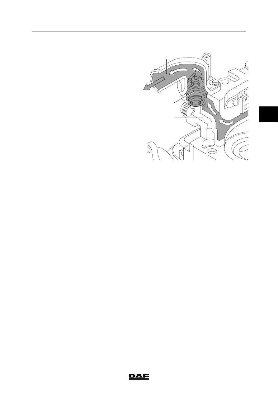
Thermostat fully opened
The temperature of the coolant has further 
increased. The supply channel (B) to the radiator 
is fully opened and the bypass channel (A) is fully 
closed.
The entire coolant circulation now flows via the 
supply channel (B) to the radiator where it is 
cooled before flowing back to the water pump.

In the event of excessive coolant temperatures, 
removing the thermostat as an emergency 
solution is not permitted.
If the thermostat is removed from the engine, 
uncooled coolant will flow to the water pump 
through the bypass (A). As a result, the coolant 
temperature will continue to rise.

M201128

1

A

B

CE-ENGINE COOLING SYSTEM

3-4

©

 200351

Description of components

3

ΧΦ65/75/85 series

2

3.3 VISCOUS FAN CLUTCH

The fan is connected to the engine by means of a 
viscous fan clutch. If, under certain 
circumstances, the heat is not sufficiently 
dissipated by the air flow passing through the 
radiator, the fan will have to draw in extra cooling 
air through the radiator. In a viscous fan clutch, 
the drive torque is transmitted by a silicone fluid.

The fan clutch is divided into two chambers. In the 
working area (1) is the rotor (2), which is 
connected to the drive flange (7). The supply 
chamber (3) rotates freely round the drive flange 
(7) and is connected to the fan. There is silicone 
fluid in the supply chamber (3). The opening (4) in 
the supply chamber (3) is closed by a valve (5). 
The valve (5) is operated by a bimetallic strip (6).

If the opening (4) in the supply chamber (3) is 
closed by the valve (5), no silicone fluid can enter 
the working area (1). The silicone fluid still 
present in the working area (1) will flow back to 
the supply chamber (3) through the bores (8). As 
only very little fluid will be left in the working area 
(1), there will be a great difference in rotating 
speed (slip) between the drive flange (7) and the 
supply chamber (3) with the fan.

When the air temperature increases, the 
bimetallic strip (6) will bend and the valve (5) will 
partially release the opening (4) in the supply 
chamber (3). Through this opening, a limited 
amount of silicone fluid can enter the working 
area (1) and flow past the rotor (2). This will cause 
friction, so that the difference in rotating speed 
(slip) between the drive flange (7) and the supply 
chamber (3) with the fan will decrease.

M201039

6

8

7

5

2

3

4
1

©

 200351

3-5

Description of components

CE-ENGINE COOLING SYSTEM

ΧΦ65/75/85 series

2

3

As the air temperature rises, the bimetallic strip 
(6) will continue to bend and the opening (4) in the 
supply chamber (3) will be fully released.
The further the opening (4) in the supply chamber 
(3) is released, the more silicone fluid will flow into 
the working area (1) and past the rotor (2). As a 
result of the increase in friction, the difference in 
rotating speed (slip) between the drive flange (7) 
and the supply chamber (3) will further decrease.

M201039

6

8

7

5

2

3

4
1

CE-ENGINE COOLING SYSTEM

3-6

©

 200351

Description of components

3

ΧΦ65/75/85 series

2


Content   ..  205  206  207  208   ..