DAF CF65, CF75, CF85 Series . Manual - part 144


  Index      DAF     DAF CF65, CF75, CF85 Series - service repair manual


Search            


Content   ..  142  143  144  145   ..


DAF CF65, CF75, CF85 Series . Manual - part 144


©

 200346

3-1

Inspection and adjustment

CAB TILTING MECHANISM

ΧΦ65/75/85 series

1

6

3. INSPECTION AND ADJUSTMENT

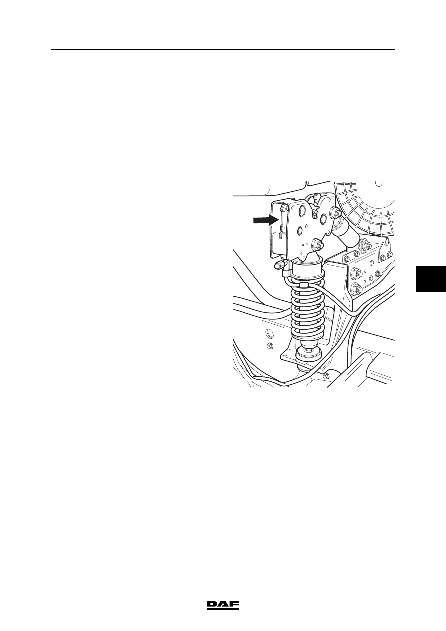
3.1 INSPECTING TILTING MECHANISM

1.

Check all pipes and connections for any 
leakage.

2.

Check the cab tilting pump for leaks.

3.

Check the lifting cylinder and the cab locks 
for leaks.

4.

Check that the pistons of the cab locks can 
move in and out freely.

Note:
A defective cab tilting mechanism is often the 
result of contaminated oil.

K1 01 659

CAB TILTING MECHANISM

3-2

©

 200346

Inspection and adjustment

6

ΧΦ65/75/85 series

1

3.2 INSPECTION AND ADJUSTMENT, PRESSURE LIMITING VALVE OF CAB 

TILTING PUMP

}

Always use a pressure gauge for 
inspection and adjustment of the 
pressure limiting valve. Too high a 
pressure may damage the tilting 
mechanism and give rise to 
extremely dangerous situations.

Checking pressure limiting valve of cab tilting 
pump
1.

Remove the pipes from the pump and plug 
the connection (D) on the pump with a 
dummy nipple.

2.

Connect a pressure gauge with a range of no 
less than 600 bar to connection (B).

3.

Bleed the pressure gauge hose.

4.

Check the oil level in the pump.

Note:
Check the oil level. Never fill the oil reservoir 
when the cab is tilted. 

5.

Put the two-way valve of the cab tilting pump 
in the "tilt forward" position. Operate the 
pump. If the measured pressure does not 
match the specified pressure, see "Technical 
data", the pressure limiting valve must be 
adjusted.

Note:
The pressure will fall slowly the moment 
pumping is stopped; this is normal. A fast 
pressure drop would indicate a defective 
two-way valve.

6.

Remove the pressure gauge and dummy 
nipples and connect the pipes.

7.

Check the oil level in the pump.

}

Too high a pressure may cause the 
end stop to be pushed out of the 
lifting cylinder, causing the cab to tilt 
forward off the chassis.

Note:
The pressure relief valve is located in the plunger 
of the cab tilting pump and can be adjusted via 
the filler opening (A).

A

C

B

D

K1 01 640

©

 200346

3-3

Inspection and adjustment

CAB TILTING MECHANISM

ΧΦ65/75/85 series

1

6

Adjusting pressure limiting valve of cab tilting 
pump
1.

Plug connection (D) on the pump with a 
dummy nipple.

2.

Connect a pressure gauge with a range of no 
less than 600 bar to connection (B).

3.

Remove filler plug (A) and fill the reservoir 
with the specified hydraulic fluid, see "Fluids 
and lubricants" specification.

Note:
Never fill the reservoir when the cab is tilted.

4.

Bleed the pressure gauge hose. Put the 
lifting cylinder cock into the "tilt forward" 
position. Operate the pump. If the pressure is 
less than the specified pressure (bar), the 
pressure relief valve should be adjusted. 
(Remember that the pressure will drop 
somewhat as soon as you stop pumping.)

5.

Remove filler plug (A) and use a suitable 
screwdriver to set the pressure relief valve in 
the plunger to the specified pressure see 
"Technical data".

6.

Remove the pressure gauge and dummy 
nipple. Connect the pipes.

7.

Check the oil level in the pump.

A

C

B

D

K1 01 640

CAB TILTING MECHANISM

3-4

©

 200346

Inspection and adjustment

6

ΧΦ65/75/85 series

1


Content   ..  142  143  144  145   ..