DAF CF65, CF75, CF85 Series . Manual - part 1126


  Index      DAF     DAF CF65, CF75, CF85 Series - service repair manual


Search            


Content   ..  1124  1125  1126  1127   ..


DAF CF65, CF75, CF85 Series . Manual - part 1126


©

 200518

3-13

Inspection and adjustment

EXPLANATORY NOTES ON THE MAINTENANCE ACTIVITIES

ΧΦ65/65 (II) series

5

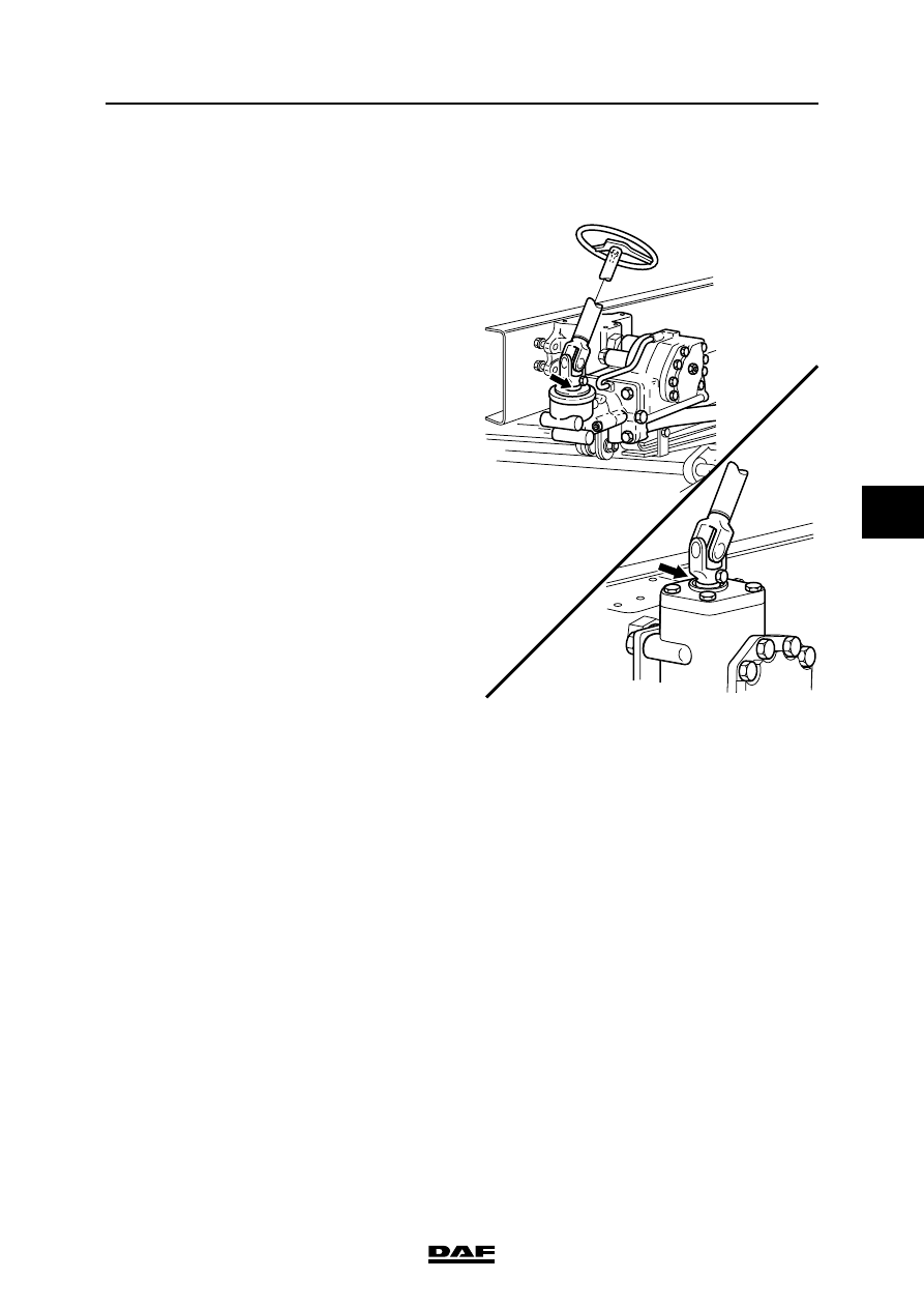
3.16 CHECKING FASTENING OF UNIVERSAL JOINT TO STEERING BOX INPUT 

SHAFT

1.

Check the universal joint for perceptible play. 

If perceptible play is detected, the affected 

part must be replaced.

2.

Check whether there is any perceptible play 

between the spline connection of the 

universal joint and the steering box input 

shaft. If perceptible play is detected, the 

splines on the universal joint and those on 

the input shaft must be checked for wear. If 

wear is detected, the affected part must be 

replaced.

3.

If there is noticeable play but the parts are 

not worn, the attachment bolt and nut must 

be replaced. Tighten the attachment bolt and 

nut to the specified torque, see "Technical 

data".

G000379-2

CF65

CF65 (II)

EXPLANATORY NOTES ON THE MAINTENANCE ACTIVITIES

3-14

©

 200518

Inspection and adjustment

5

ΧΦ65/65 (II) series

3.17 CHECKING THE STEERING BALL JOINT SLEEVE FOR DAMAGE

Inspection, locking devices and dust cover
1.

Check that the steering ball joint dust cover 

or seal is not damaged. Replace the steering 

ball joint if damaged.

2.

If a castle nut is fitted, check that the locking 

devices are present and undamaged.

S7 00 592

©

 200518

3-15

Inspection and adjustment

EXPLANATORY NOTES ON THE MAINTENANCE ACTIVITIES

ΧΦ65/65 (II) series

5

3.18 CHECKING THE STEERING BALL JOINTS

Checking axial steering ball joint play
1.

Check the axial steering-ball joint play using 

special tool (DAF no. 1329426)

2.

First jack up the axle until the wheels come 

off the ground and put the axle on stands.

3.

Make sure that the castle nut split pin 

(if fitted) at the nut does not come into 

contact with the head of the threaded end.

4.

Screw the thrust washer (8) on to the 

threaded spindle.

5.

Fit the spring retainer (3), spring (4) and 

pressure sleeve (6) into bracket (1). Fit the 

locking screw (5). It should be possible to 

move the pressure sleeve (6) freely.

Note:

Fit the correct pressure sleeve (6).

The pressure sleeve (6) must abut the outer 

edge of the steering ball joint (7).

6.

Loosen thrust bolt (2) until the pressure 

sleeve (6) with the flange abuts the bracket 

(A = 0 mm).

7.

Fit the special tool over the steering ball joint 

(7) and turn the threaded spindle (9) by hand 

until the special tool is tight around the 

steering ball joint (7).

8.

Tighten thrust bolt (2) until its head abuts 

bracket (1).

9.

Measure play "A" between the pressure 

sleeve and the bracket using a feeler gauge. 

Compare the reading with the maximum 

permissible steering ball joint play, see 

"Technical data". 

If necessary, replace the steering ball joint.

9

8

7

6

5

4

3

2

A

1

S700426

EXPLANATORY NOTES ON THE MAINTENANCE ACTIVITIES

3-16

©

 200518

Inspection and adjustment

5

ΧΦ65/65 (II) series

3.19 CHECKING THE STEERING OIL LEVEL

1.

Check the steering oil level when the engine 

is not running.

2.

Clean the dipstick and its immediate 

surroundings to prevent any oil from entering 

the reservoir.

3.

Check the fluid level in the reservoir using 

the dipstick.

4.

The fluid level should be between the marks 

when the steering oil is "cold".

Note:

When the steering oil is at operating 

temperature, the level may be above the top 

mark on the dipstick.

S7 00 676


Content   ..  1124  1125  1126  1127   ..