Content .. 999 1000 1001 1002 ..
DAF CF65, CF75, CF85 Series . Manual - part 1001
©
200423
3-5
Removal and installation
STEERED TRAILING SWIVEL AXLE
ΧΦ65/75/85 series
7
7
3.2 REMOVAL AND INSTALLATION, TRACK ROD
Removing the track rod
1.
Remove the wheel speed sensor and the
connector bracket.
Note:
When the track rod has been removed, the
swivel axle can be at such an angle that the
wheel speed sensor is damaged, which can
damage the wheel speed sensor ring.
2.
Remove the attachment nuts. These nuts
should not be re-used.
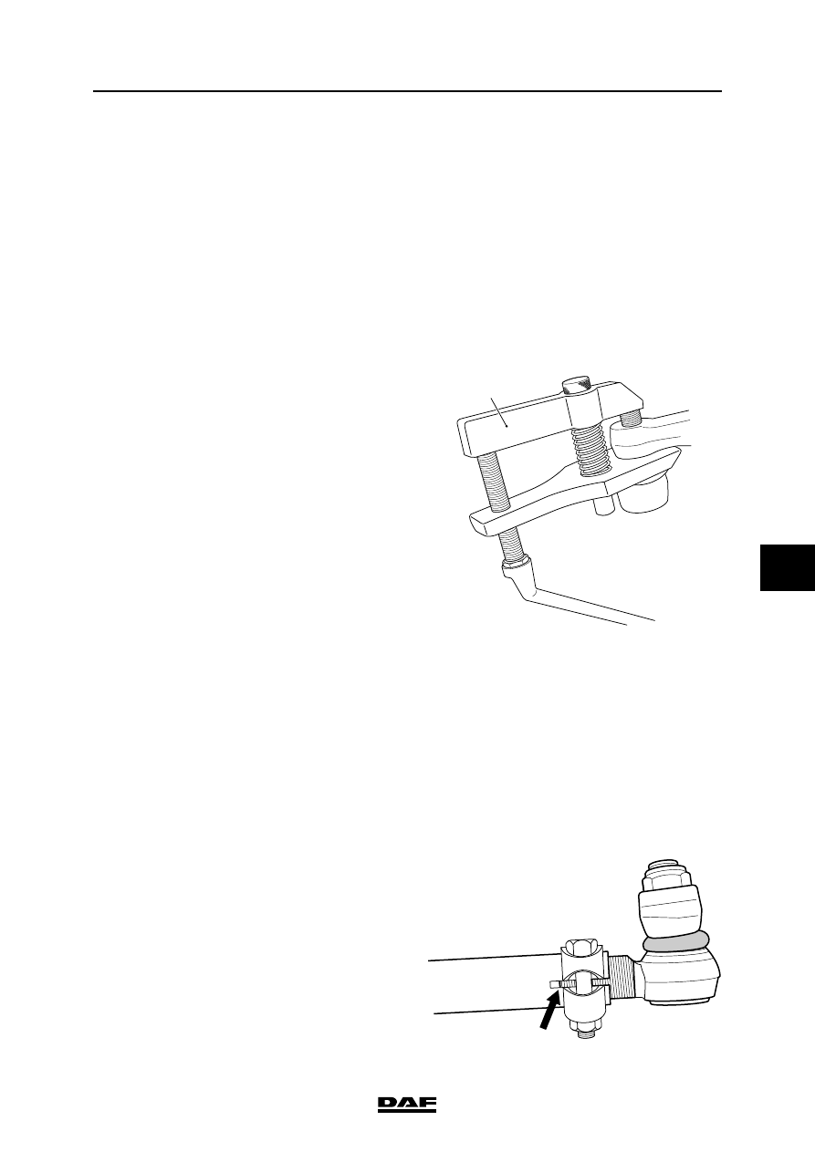
3.
Remove the ball ends from the track rod
arms using a ball end puller (A).
Installation of track rod
1.
If installing a new track rod, copy the settings
of the track rod to be replaced.
2.
Check the ball end thread for damage before
fitting a new self-locking nut. See 'Inspection
and adjustment'.
Fitting a new self-locking nut to a
ball end with a damaged thread may
lead to dangerous situations.
3.
Clean the tapered contact surfaces of both
the track rod balls and the track rod arms.
The tapered surfaces should be absolutely
free from dirt, grease and paint.
4.
Fit the track rod.
5.
Fit a new self-locking nut to the ball end.
Apply locking compound to the nut. See
'Technical data'.
6.
Tighten the new self-locking nuts to the
specified torque. See 'Technical data'.
7.
Check the axle toe and adjust, if necessary.
See 'Inspection and adjustment'.
8.
Check whether the threaded ends of the ball
joints are fully engaged by the clamping
pieces.
9.
Check whether the clamping piece bolts are
tightened to the specified tightening torque.
See 'Technical data'.
10. Fit the wheel speed sensor and the
connector bracket.
S7 00 555
A
}
S7 00 539