DAF XF105. Manual - part 76
0
©
200528
1-9
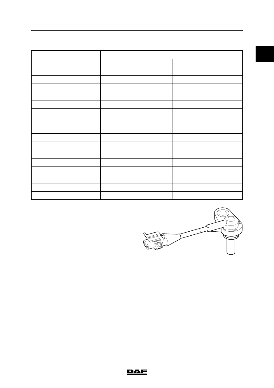
DMCI engine management system
TECHNICAL DATA
XF105 series
Resistance in relation to measured temperature
Coolant temperature sensor
Temperature (
C)
Resistance (
)
Minimum
Maximum
- 40
87134
98852
- 30
44876
50910
-20
24215
27471
-10
13703
15545
0
7914
8978
10
4752
5390
20
2948
3344
40
1224
1388
50
8167
927
60
558
632
70
390
442
80
278
311
90
201
227
100
148
168
110
110
124
120
83
95
i401003
Model
NTC