DAF 95XF. Manual - part 534


  Index      DAF     DAF 95XF Series - service repair manual


Search            


Content   ..  532  533  534  535   ..


DAF 95XF. Manual - part 534


EXPLANATORY NOTES ON THE MAINTENANCE ACTIVITIES

Inspection and adjustment

3-12

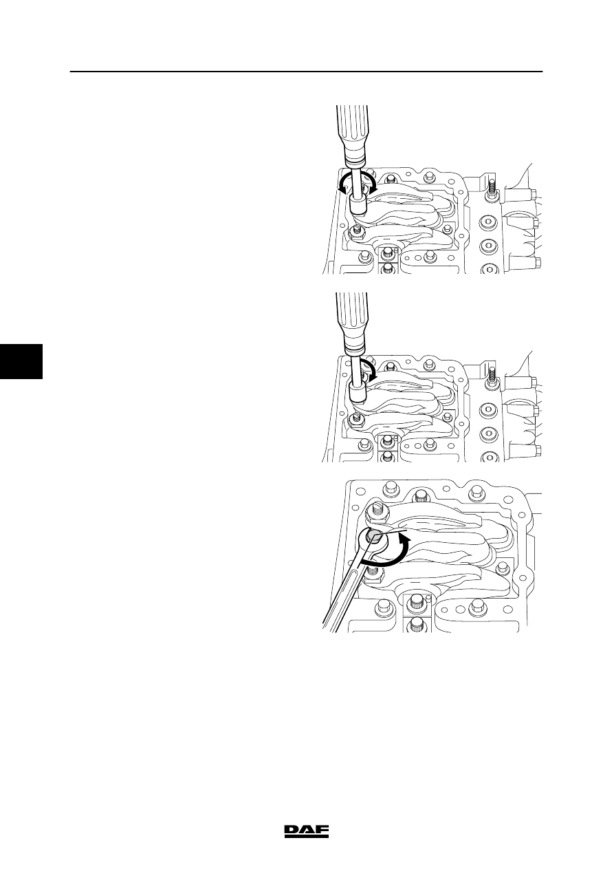
Adjusting the unit-injector
1.

Slacken the lock nut of the adjusting bolt.

2.

Turn the adjusting bolt three to four times
clockwise and anti-clockwise. This will force
the fuel beneath the injector plunger out,
thus moving the injector plunger
downwards.

M2137

3.

Then screw the adjusting bolt clockwise
until there is clear, considerable resistance.
Do not turn the adjusting bolt further in
clockwise direction to avoid damage.

M2138

4.

Turn the adjusting bolt 120

ٛ

anti-clockwise.

This equals a clearance of 0.55 mm (setting
value may be between 0.50 and 0.75 mm).

5.

Hold the adjustment bolt in this position and
tighten the lock nut to the specified
tightening torque, see “Technical data”.

M2139

5

 200424

Inspection and adjustment

EXPLANATORY NOTES ON THE MAINTENANCE ACTIVITIES

3-13

3.10 INSPECTION AND ADJUSTMENT, C-BRAKE PLAY

VF engine

Note:
-

The C-brake must be adjusted when the
engine is cold ( <60

°C).

-

Use a dial gauge for C-brake adjustments.

-

Each cylinder has three rockers:
1.

The rocker for the exhaust valves (1)

2.

The rocker for the unit injector (2)

3.

The rocker for the inlet valves (3).

M2146

1

2

3

3

2

1

-

For a correct setting of the C-brake, use the
set marks shown on the accessory drive
pulley (1) for the air-conditioning
compressor and the water pump.

-

The direction of rotation of the crankshaft is
clockwise, as seen from the front of the
engine.

-

Cylinder 1 is on the timing-gear end, and
cylinder 6 on the flywheel end.

-

The injection sequence is 1-5-3-6-2-4.

M2147

1

1 2 3 4 5 6

5

 200424

EXPLANATORY NOTES ON THE MAINTENANCE ACTIVITIES

Inspection and adjustment

3-14

-

The C-brakes of the specified cylinders can
be set using the table below and the marks
on the drive pulley and on the timing cover.

Marks on drive pulley:
Adjustment of cylinder C-brake:

A

5 or 2

B

3 or 4

C

1 or 6

1.

Disconnect the battery earth lead.

2.

Remove the valve covers. See “Removal
and installation”.

3.

Rotate the drive pulley (in the direction of
rotation of the crankshaft) using the
attachment nut on the pulley, until the “A”
marking is in line with the marking on the
timing cover.

4.

Check that the inlet and exhaust valves of
cylinder 5 are closed.

Note:
The valves are closed if both rockers can be
moved from side to side.
If necessary, rotate the drive pulley through
360

° until the “A” marking is once again in

line with the marking on the timing cover.
Now set the C-brake of cylinder 5.

A

M2148

A

B

C

A

M2142

5.

Slacken the lock nut of the adjusting bolt.

6.

Tighten the adjusting bolt clockwise until
you clearly feel resistance (the C-brake
plunger is now in contact with the
exhaust-valves bridge).

M2153

5

 200424

Inspection and adjustment

EXPLANATORY NOTES ON THE MAINTENANCE ACTIVITIES

3-15

7.

Install a dial gauge.

8.

Set the dial gauge to “0”.

9.

Turn the adjusting bolt counter-clockwise
until the value on the dial gauge equals the
C-brake setting value, see “Technical data”.

Note:
The setting value is also shown on the
shield (1) fitted on the C-brake housing.

10. Tighten the lock nut to the specified

tightening torque. See “Technical data”.
Use special tool (DAF no. 1240042).

11. Repeat this adjustment procedure for the

remaining cylinders. Consult the following
table to this end.

Marks on drive pulley:
Adjustment of cylinder C-brake:

A

5

B

3

C

6

A

2

B

4

C

1

12. Fit the valve covers. See “Removal and

installation”.

M2152

0

5

 200424


Content   ..  532  533  534  535   ..