DAF 95XF. Manual - part 414


  Index      DAF     DAF 95XF Series - service repair manual


Search            


Content   ..  412  413  414  415   ..


DAF 95XF. Manual - part 414


4

XE ENGINE FUEL SYSTEM

General

95

XF series

2-12

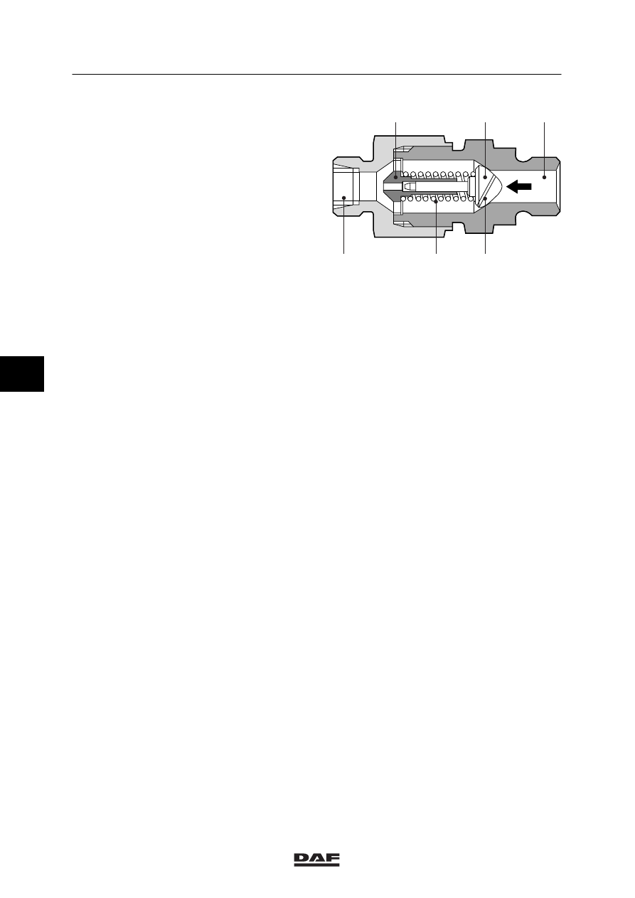
Pressure-relief valve
To ensure a proper pump unit fill rate, a
pressure-relief valve is fitted on the return
connection of the pump casing.

The fuel flows from inlet (1) to outlet (4) via
piston (2) and guide pin (3). The fuel meets
resistance as a result of spring (5). This results
in a pressure-relief valve opening pressure of
approximately 2.8 bar.

A diagonal bore (6) is drilled in piston (2). This
bore serves for bleeding the fuel system.

i400360

3

2

1

6

5

4

5

©

 0008

4

95

XF series

Inspection and adjustment

XE ENGINE FUEL SYSTEM

3-1

3.  INSPECTION AND ADJUSTMENT

3.1

CHECKING THE FUEL LEVEL ELEMENT

To avoid deforming the fuel tank,
the pressure in the fuel tank may
not exceed 0.4 bar.

1.

Fit a pressure reducing valve connection to
a fuel filler cap (without bleeding) and
connect it to the fuel tank.

2.

Pressurise the fuel tank (maximum 0.1 bar).

3.

Slowly increase the pressure, until one can
hear the system blow off via the small
overpressure valve and check the opening
pressure of the fuel level element, see main
group “Technical data”.

4.

Depressurise the fuel tank and remove the
fuel-tank cap with air connection.

5.

Note:
To prevent dirt from entering, first clean the
exterior of the fuel tank.

Remove the fuel level element.

6.

Check the angular rotation of the fuel level
element, see main group “Technical data”.

I400141

5

©

 0008

4

XE ENGINE FUEL SYSTEM

Inspection and adjustment

95

XF series

3-2

3.2

INSPECTION AND ADJUSTMENT OF INJECTOR OPENING PRESSURE

Fuel or test fluid discharged by an
injector may penetrate the skin and
be very harmful to your health.
Make sure the fuel jet is discharged
into a suitable container.

Checking the opening pressure with an
injector test pump
-

The opening pressures of the injectors can
be tested using an injector test pump
(DAF no. 0694966). The advantage of this
method is that the injectors need not be
removed from the engine.

Instructions for the use of the injector test
pump
Before the injector testing pump is used, it must
first be bled.
1.

Remove the pump reservoir filler cap and fill
the reservoir with test fluid. The fluid level
must be approximately 1 cm beneath the
top rim.

2.

Tilt the pump until the line with the word
“BLEED” is in a horizontal position.

M4059

BLEED

5

©

 0008

4

95

XF series

Inspection and adjustment

XE ENGINE FUEL SYSTEM

3-3

3.

Depress the bleed pin (1) and
simultaneously turn the crank (2) clockwise
to the stop.
During this operation, air bubbles will come
to the surface in the reservoir. Now turn
back the crank, fill the reservoir again and
turn the crank until no more air bubbles
come to the surface.
Now release the bleed pin. Continue turning
the crank until fuel escapes on the delivery
side.

4.

If necessary, fill the fuel reservoir and screw
back the cap.

5.

The pump is now ready for use.

Inspecting the injector opening pressure
1.

Remove the injection lines in sets of three,
see chapter “Removal and installation”.
Immediately plug the connection openings
on the fuel pump.

2.

Connect the injection line (supplied with the
injector test pump) to the injector to be
tested and to the test pump. Keep the test
pump approximately in horizontal position.

3.

Loosen the test pump filler cap by half a
turn, so that air can enter the reservoir.

4.

Turn the crank of the test pump clockwise.
The compression stroke starts. Watch the
fluid level in the test pump.

5.

Carefully determine the opening pressure of
the injector. There is no harm in repeating
the test twice or three times. If the test is
repeated too often, however, the test fluid
deposited on the piston may cause damage
to the engine when it is started.

6.

Reinstall the injection lines, see chapter
“Removal and installation”.

2

A

1

M4058

i 400190

5

©

 0008


Content   ..  412  413  414  415   ..