DAF 95XF. Manual - part 332
5
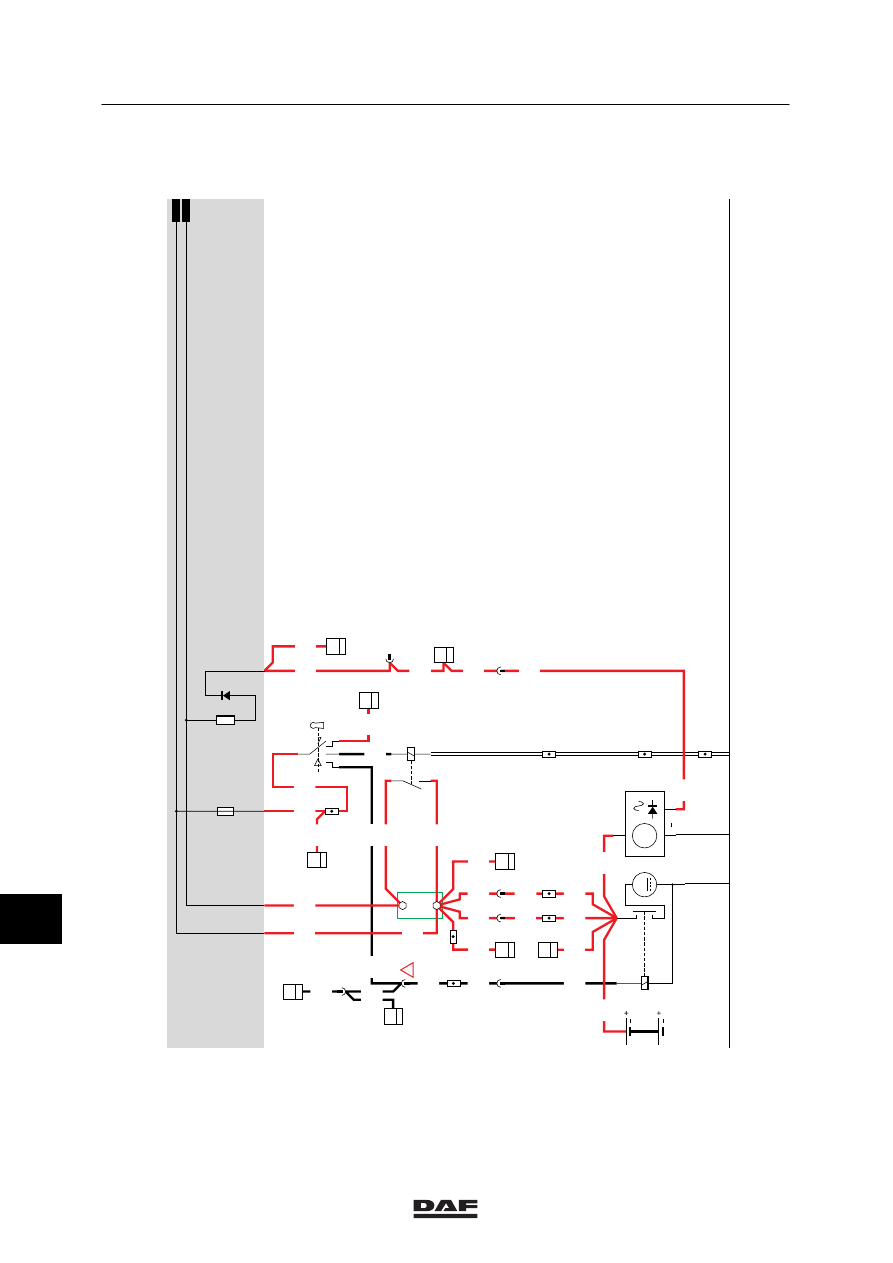
MODIFICATIONS TO THE ELECTRICAL INSTALLATION
Modifications to the electrical installation from chassis number 0E473500
3-14
A
114
1000
1000
1000
D853
B6
7
1020
1316630/13-23
EL000253
A
4001
1010
1000
A500
1/416
1/417
15/402
G525
G525
G014
1
3
1000
27
114
!
4009
4009
1000
4002
1100
1100
1/412
2/412
4/412
6/412
1010
G178
30
1
13/402
1020
1020
A040
7
42
1
114
1020
1020
1020
1000
4002
1000
B
114
1000
1000
1000
4002
D827
A4
41
D550
45
6
1100
4002
C539
8
383
30
87
86
85
G015
1000
50
B010
M
31
30
G
3
D
B+
D+
A502
1130
G178
85
1
4002
1000
E043
A1
23
1000
E168
A1
21
D878
1010
1000
E037
15A
1000
1010
D668
B036
1024
1020
1
2
3
4
5
6
7
8
9
10
11
12
13
14
15
16
17
18
19
20
21
22
23
24
25
26
27
28
29
30
31
32
33
34
35
36
37
38
39
40
41
42
43
44
45
46
47
48
49
50
51
52
53
2
383
4002
11
ǹ 0209