DAF 95XF. Manual - part 230
5
General
COMPONENTS
1-5
2.
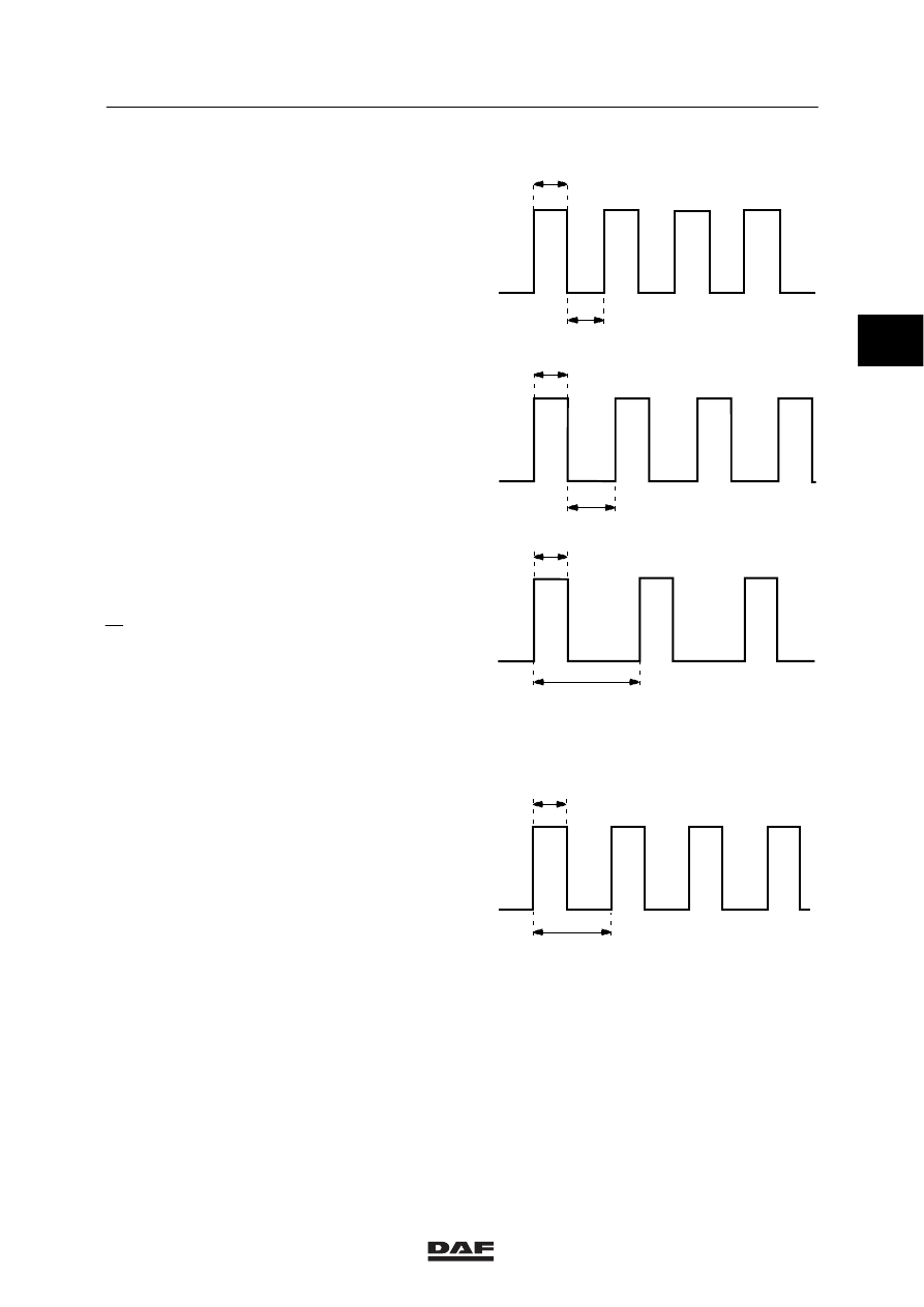
Square-wave signal
Square-wave signals only have two voltage
levels, both of which - in principle - have the
same duration (t1 equals t2).
If the duration is different for the two levels (t1 is
not equal to t2), the signal is called a “pulse
train”.
Duty-cycle
The duty cycle is the ratio between the two
voltage levels expressed as a percentage.
A
x 100%
B
The voltage level ratio of a “pulse train” may
change (for example, when the vehicle speed
increases).
If the number of pulses per unit of time
increases, the duty cycle reading will also
increase.
Voltage
An increase in the number of pulses per unit of
time will not only give higher duty cycle readings
but also a higher mean voltage.
+
0
t
2
t
1
t
1
t
2
0
+
A
B
0
+
0
+
A
B
W 5 01 001
2
ǹ 9811