DAF 95XF. Manual - part 144


  Index      DAF     DAF 95XF Series - service repair manual


Search            


Content   ..  142  143  144  145   ..


DAF 95XF. Manual - part 144


6

Removal and installation

BRAKE COMPONENTS

2-15

2.6 REMOVAL AND INSTALLATION, BRAKE SHOES

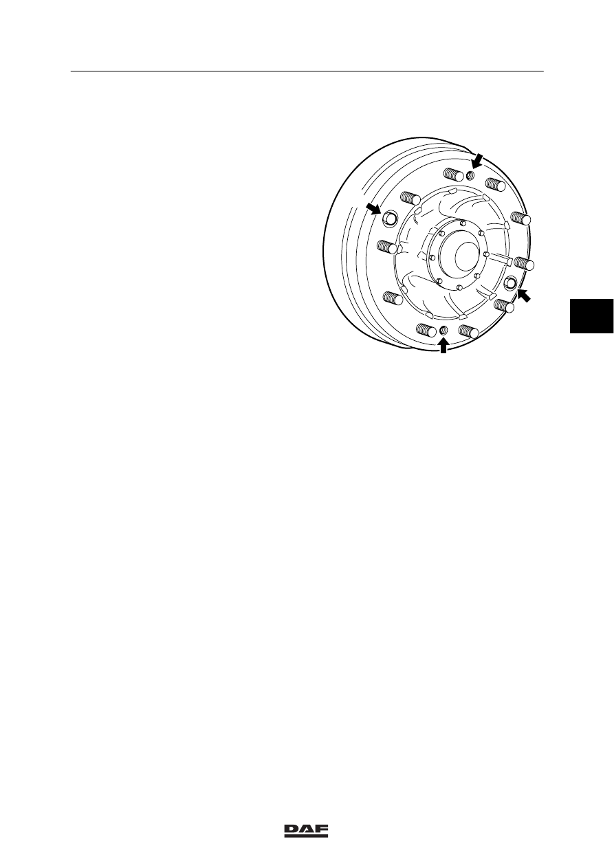
Removal of the brake drum
1.

Pressurise the air system.

2.

Place chocks in front of and behind the
wheels of another axle on which you are not
working.

3.

Release the parking brake by the
parking-brake valve or by removing the
release bolts from the spring-brake
cylinders.

4.

Fully reset the automatic slack adjuster.

5.

Unscrew the wheel nuts.

6.

Jack up the axle in question.

7.

Support the axle with stands.

8.

Remove the wheels.

9.

Remove the two attachment bolts (A) from
the brake drum.

10. Insert two jack screws in the threaded

holes (B).

11. Note:

Never use airtools to tighten the jack
screws.

Evenly tighten the jack screws manually.
This will put pressure on the brake drum.
Use a copper punch to remove the brake
drum from the hub. Use lifting gear to
remove the brake drum.

R600144

B

B

A

A

4

ǹ 0006

6

BRAKE COMPONENTS

Removal and installation

2-16

Installation of the brake drum
1.

Clean the fitting edges of the brake drum
and the wheel rim with a steel wire brush.

2.

Grease the fitting edge lightly with grease.
This grease layer should prevent the brake
drum from “rusting tight”.

3.

Remove the jack screws from the brake
drum.

4.

Fit the brake drum using the lifting gear.

5.

Fit two wheel nuts opposite one another.

6.

Tighten these wheel nuts evenly, until the
brake drum is correctly on the hub.

7.

Remove the wheel nuts.

8.

Fit the attachment bolts for the brake drum.

9.

Fit the wheels and wheel nuts and tighten
the nuts evenly, in the correct order
(see group 7).

10. Adjust the brakes, see chapter

“Inspection and adjustment”.

11. Remove the jack and chocks from the rear

wheels. If the spring-brake cylinder was
mechanically released, the release bolt
should be screwed back in and tightened to
a torque of 30 - 35 Nm. The pressure in the
spring-brake cylinder circuit should be at
least 5 bar.

4

ǹ 0006

6

Removal and installation

BRAKE COMPONENTS

2-17

2.7 REMOVAL AND INSTALLATION, BRAKE SHOES

Removal of the brake shoes
1.

Remove the brake drum.

2.

Remove the lock rings, felt rings and
retainer rings from the side of the brake
shoe.

3.

Remove the lock bolts or lock studs from
the anchor pins.

R600145

4

ǹ 0006

6

BRAKE COMPONENTS

Removal and installation

2-18

4.

Remove the anchor pins.

5.

First remove the bottom brake shoe by
moving it outwards from the anchor pin
holes.

6.

Unhook the return spring, and remove the
upper brake shoe.

Installation of the brake shoes
1.

Clean all parts.

2.

Lubricate the anchor pins, roller cams and
contact surfaces of the brake shoes with
Copaslip.

3.

Fit the return spring in the brake shoes.

4.

First fit the upper brake shoe in position,
then the lower shoe.

5.

Fit the anchor pins. Ensure that the
flattened section is placed beneath the bore
in the back plate.

6.

Fit the felt ring, retainer ring and lock ring to
the anchor pin.

7.

Lock the anchor pins with the lock bolt and
fit the locking wire, or lock the anchor pins
using a stud.

8.

Fit the dust plates.

9.

Fit the brake drum.

R600146

4

ǹ 0006


Content   ..  142  143  144  145   ..