Citroen C5 Dag (2010 year). Instruction - part 14
XI
186
P R A C T I C A L I N F O R M A T I O N
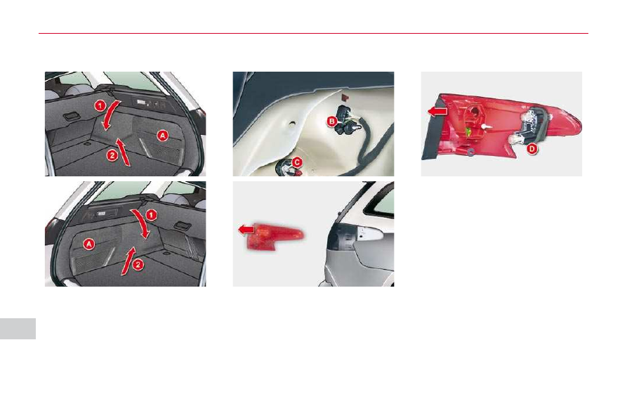
Wing-mounted lamps
Remove the lateral boot trim A .
To do so:
Pull it towards towards the inside
of the boot.
Pull it upwards.
Disconnect the connector B
.
Unscrew the fi xing screw C .
Remove the lamp from its housing.
Detach the bulb holder D
.
Replace the faulty bulb.
Refi t the bulb holder D .
Place the lamp in its housing.
Screw in the fi xing screw C .
Refi t the connector B .
Refi t the trim A .
You can use the wheelbrace to screw
or unscrew the fi xing screw C .