RAM 5500 Chassis Cab (2017 year). Manual - part 8


  Index      RAM     RAM 5500 Chassis Cab (2017 year) - manual in english


Search            copyright infringement  


Content      ..     6      7      8      9     ..


RAM 5500 Chassis Cab (2017 year). Manual - part 8


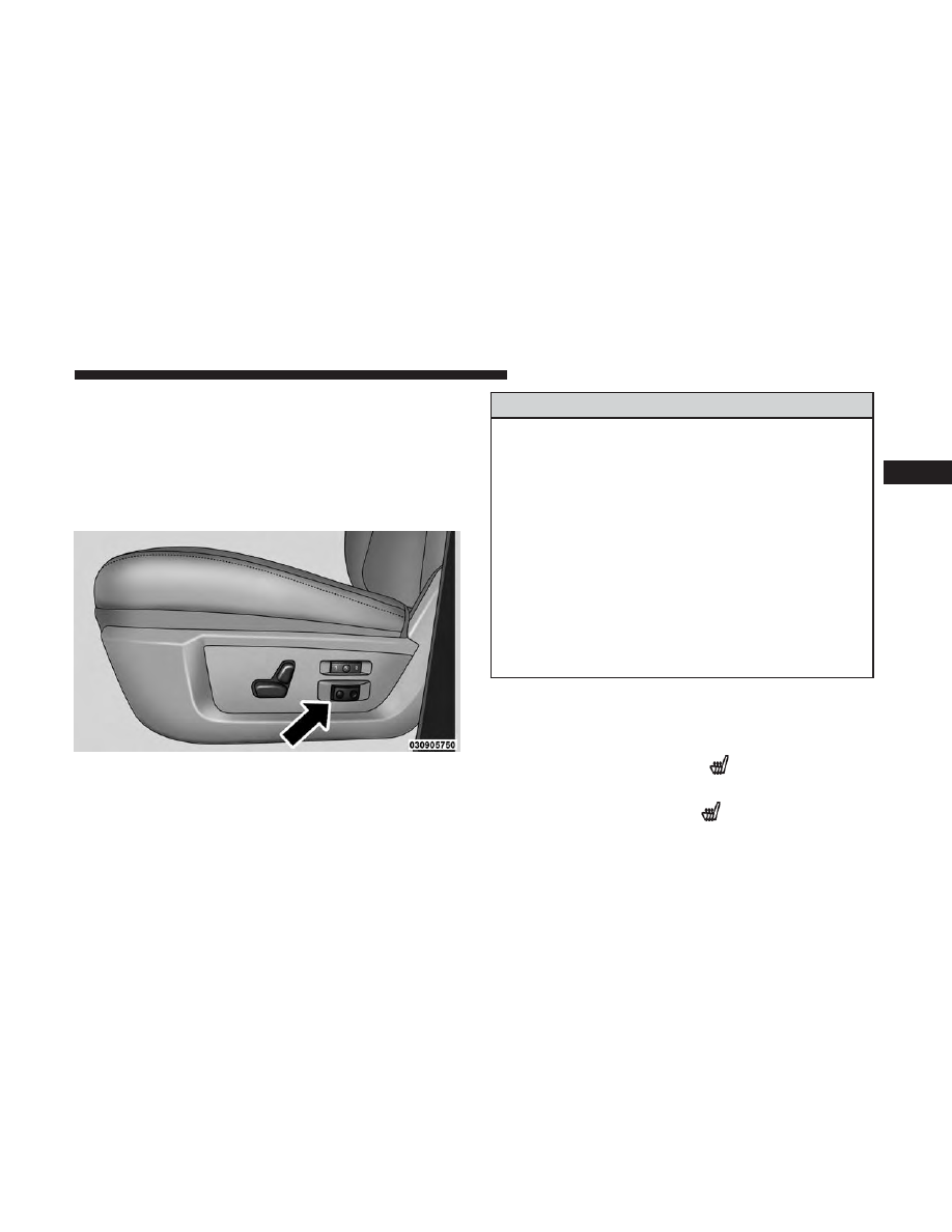
Power Lumbar — If Equipped

Vehicles equipped with power driver or passenger seats
may be also be equipped with power lumbar. The power
lumbar switch is located on the outboard side of the power
seat. Push the switch forward to increase the lumbar
support. Push the switch rearward to decrease the lumbar
support.

Heated Seats — If Equipped

On some models, the front and rear seats may be equipped
with heaters located in the seat cushions and seat backs.

WARNING!

• Persons who are unable to feel pain to the skin

because of advanced age, chronic illness, diabetes,
spinal cord injury, medication, alcohol use, exhaus-
tion or other physical condition must exercise care
when using the seat heater. It may cause burns even
at low temperatures, especially if used for long
periods of time.

• Do not place anything on the seat or seatback that

insulates against heat, such as a blanket or cushion.
This may cause the seat heater to overheat. Sitting in
a seat that has been overheated could cause serious
burns due to the increased surface temperature of the
seat.

Front Heated Seats

The front heated seats control buttons are located within
the climate or controls screen of the touchscreen.

• Press the heated seat button

once to turn the HI

setting On.

• Press the heated seat button

a second time to turn

the LO setting On.

Lumbar Control Switch

3

UNDERSTANDING THE FEATURES OF YOUR VEHICLE

117

-------------------------------------------------------------------------------------------------------------------------------------------------------------

• Press the heated seat button

a third time to turn the

heating elements OFF.

If the HI-level setting is selected, the system will automati-
cally switch to LO-level after approximately 60 minutes of
continuous operation. At that time, the display will change
from HI to LO, indicating the change. The LO-level setting
will turn OFF automatically after approximately 45 min-
utes.

NOTE:

The engine must be running for the heated seats to

operate.

Vehicles Equipped With Remote Start

On models that are equipped with remote start, the heated
seats can be programed to come on during a remote start.

If your vehicle is equipped with a touchscreen, this feature
can be programmed through the Uconnect system. Refer to
“Uconnect Settings” in “Understanding Your Instrument
Panel” for further information.

Rear Heated Seats

On some models, the two outboard seats are equipped
with heated seats. The heated seat switches for these seats
are located on the rear of the center console.

There are two heated seat switches that allow the rear
passengers to operate the seats independently. You can
choose from HI, LO or OFF heat settings. Amber indicator
lights in each switch indicate the level of heat in use. Two
indicator lights will illuminate for HI, one for LO and none
for OFF.

Push the switch once to select HI-level heating.
Push the switch a second time to select LO-level
heating. Push the switch a third time to shut the
heating elements OFF.

NOTE:

• Once a heat setting is selected, heat will be felt within

two to five minutes.

• The engine must be running for the heated seats to

operate.

When the HI-level setting is selected, the heater will
provide a boosted heat level during the first four minutes
of operation. Then, the heat output will drop to the normal
HI-level. If the HI-level setting is selected, the system will
automatically switch to LO-level after approximately 60
minutes of continuous operation. At that time, the number

118

UNDERSTANDING THE FEATURES OF YOUR VEHICLE

-------------------------------------------------------------------------------------------------------------------------------------------------------------

of illuminated LEDs changes from two to one, indicating
the change. The LO-level setting will turn OFF automati-
cally after approximately 45 minutes.

Ventilated Seats — If Equipped

Located in the seat cushion are small fans that draw the air
from the passenger compartment and pull air through fine
perforations in the seat cover to help keep the driver and
front passenger cooler in higher ambient temperatures. The
fans operate at two speeds, HI and LO.

The front ventilated seats control buttons are located
within the climate or controls screen of the touchscreen.

• Press the ventilated seat button

once to choose HI.

• Press the ventilated seat button

a second time to

choose LO.

• Press the ventilated seat button

a third time to turn

the ventilated seat OFF.

NOTE:

The engine must be running for the ventilated

seats to operate.

Vehicles Equipped With Remote Start

On models that are equipped with remote start, the ventilated
seats can be programed to come on during a remote start.

If your vehicle is equipped with a touchscreen, this feature
can be programmed through the Uconnect system. Refer to
“Uconnect Settings” in “Understanding Your Instrument
Panel” for further information.

Manual Seat Adjuster — If Equipped

Both front seats are adjustable forward or rearward. The
manual seat adjustment handle is located under the seat
cushion at the front edge of each seat.

While sitting in the seat, pull up on the handle and slide the
seat forward or backward. Release the bar once you have
reached the desired position. Then, using body pressure,

Manual Seat Adjuster

3

UNDERSTANDING THE FEATURES OF YOUR VEHICLE

119

-------------------------------------------------------------------------------------------------------------------------------------------------------------

move forward and rearward on the seat to be sure that the
seat adjusters have latched.

WARNING!

• Adjusting a seat while driving may be dangerous.

Moving a seat while driving could result in loss of
control which could cause a collision and serious
injury or death.

• Seats should be adjusted before fastening the seat

belts and while the vehicle is parked. Serious injury or
death could result from a poorly adjusted seat belt.

Reclining Rear Seats — If Equipped

The recliner handle is located on the outside of the seat
cushion. To adjust the seatback, lift upward on the handle,
lean back on the seatback and when you reach the desired
position, release the handle.

Rear Seat Recliner Handle

120

UNDERSTANDING THE FEATURES OF YOUR VEHICLE

-------------------------------------------------------------------------------------------------------------------------------------------------------------

WARNING!

Do not ride with the seatback reclined so that the
shoulder belt is no longer resting against your chest. In
a collision you could slide under the seat belt, which
could result in serious injury or death.

40-20-40 Front Bench Seat — If Equipped

The seat is divided into three segments. The outboard seat
portions are each 40% of the total width of the seat. On
some models the back of the center portion (20%) easily
folds down to provide an armrest/center storage compart-
ment.

Head Restraints

Head restraints are designed to reduce the risk of injury by
restricting head movement in the event of a rear impact.

Head restraints should be adjusted so that the top of the
head restraint is located above the top of your ear.

WARNING!

• All occupants, including the driver, should not oper-

ate a vehicle or sit in a vehicle’s seat until the head
restraints are placed in their proper positions in
order to minimize the risk of neck injury in the event
of a crash.

• Head restraints should never be adjusted while the

vehicle is in motion. Driving a vehicle with the head
restraints improperly adjusted or removed could
cause serious injury or death in the event of a
collision.

3

UNDERSTANDING THE FEATURES OF YOUR VEHICLE

121

-------------------------------------------------------------------------------------------------------------------------------------------------------------

Front Head Restraints

To raise the head restraint, pull upward on the head
restraint. To lower the head restraint, push the adjustment
button located on the base of the head restraint and push
downward on the head restraint.

To remove the head restraint, raise it up as far as it can go
then push the adjustment button and the release button at
the base of each post while pulling the head restraint up. To
reinstall the head restraint, put the head restraint posts into
the holes then adjust it to the appropriate height.

WARNING!

• A loose head restraint thrown forward in a collision

or hard stop could cause serious injury or death to
occupants of the vehicle. Always securely stow re-
moved head restraints in a location outside the
occupant compartment.

(Continued)

Adjustment Buttons

1 — Release Button
2 — Adjustment Button

122

UNDERSTANDING THE FEATURES OF YOUR VEHICLE

-------------------------------------------------------------------------------------------------------------------------------------------------------------

WARNING! (Continued)

• ALL the head restraints MUST be reinstalled in the

vehicle to properly protect the occupants. Follow the
re-installation instructions above prior to operating
the vehicle or occupying a seat.

NOTE:

Do not reposition the head restraint 180 degrees to

the incorrect position in an attempt to gain additional
clearance to the back of the head.

Rear Head Restraints

The rear seats are equipped with adjustable and removable
head restraints. To raise the head restraint, pull upward on
the head restraint. To lower the head restraint, push the
adjustment button located on the base of the head restraint
and push downward on the head restraint.

To remove the head restraint, push the adjustment button
and the release button while pulling upward on the whole
assembly. To reinstall the head restraint, put the head
restraint posts into the holes and adjust it to the appropri-
ate height.

NOTE:

To remove outboard restraints, the rear seat bottom

must be folded up.

WARNING!

A loose head restraint thrown forward in a collision or
hard stop could cause serious injury or death to occu-
pants of the vehicle. Always securely stow removed
head restraints in a location outside the occupant
compartment.

Release/Adjustment Buttons

1 — Release Button
2 — Adjustment Button

3

UNDERSTANDING THE FEATURES OF YOUR VEHICLE

123

-------------------------------------------------------------------------------------------------------------------------------------------------------------

NOTE:

• The rear center head restraint (Crew Cab and Quad Cab)

has only one adjustment position that is used to aid in
the routing of a tether. Refer to “Occupant Restraints” in
“Things to Know Before Starting Your Vehicle” for
further information.

• Do not reposition the head restraint 180 degrees to the

incorrect position in an attempt to gain additional clear-
ance to the back of the head.

WARNING!

ALL the head restraints MUST be reinstalled in the
vehicle to properly protect the occupants. Follow the
re-installation instructions above prior to operating the
vehicle or occupying a seat.

DRIVER MEMORY SEAT — IF EQUIPPED

This feature allows the driver to store up to two different
memory profiles for easy recall through a memory switch.
Each memory profile contains desired position settings for
the driver seat, side mirrors, adjustable pedals (if
equipped) and a set of desired radio station presets. Your

Remote Keyless Entry key fob can also be programmed to
recall the same positions when the UNLOCK button is
pushed.

NOTE:

Your vehicle is equipped with two key fobs, one

key fob can be linked to memory position 1 and the other
key fob can be linked to memory position 2.

The memory seat buttons are located on the outboard side
of the drivers seat cushion.

Memory Seat Buttons

124

UNDERSTANDING THE FEATURES OF YOUR VEHICLE

-------------------------------------------------------------------------------------------------------------------------------------------------------------

Programming The Memory Feature

To create a new memory profile, perform the following:

1. Cycle the vehicles ignition to the ON/RUN position (do

not start the engine).

2. Adjust all memory profile settings to desired prefer-

ences (seat, side mirrors, adjustable pedals and radio
station presets).

3. Push and release the S (Set) button on the memory

switch.

4. Within five seconds, push and release either of the

memory buttons (1) or (2). The instrument cluster dis-
play will show which memory position has been set.

NOTE:

• Memory profiles can be set without the vehicle in PARK,

but the vehicle must be in PARK to recall a memory
profile.

• To set a memory profile to your key fob, refer to

“Linking And Unlinking The Remote Keyless Entry Key
Fob To Memory” in this section.

Linking And Unlinking The Remote Keyless Entry
Key Fob To Memory

Your key fobs can be programmed to recall one of two
pre-programmed memory profiles by pushing the UN-
LOCK button on the key fob.

NOTE:

Before programming your key fobs to memory the

feature has to be selected.

• If your vehicle is equipped with a touchscreen, you must

select the “Memory To Fob” feature through the
Uconnect system. Refer to “Uconnect Settings ” in
“Understanding Your Instrument Panel” for further in-
formation.

• If your vehicle is not equipped with a touchscreen, you

must select the “Key Fob Linked To Memory” feature
through the instrument cluster display. Refer to “Instru-
ment Cluster Display” in “Understanding Your Instru-
ment Panel” for further information.

To program your key fobs, perform the following:

1. Cycle the vehicles ignition to the Off position.

2. Select desired memory profile (1) or (2).

3

UNDERSTANDING THE FEATURES OF YOUR VEHICLE

125

-------------------------------------------------------------------------------------------------------------------------------------------------------------

NOTE:

If a memory profile has not already been set, refer

to

⬙Programming The Memory Feature⬙ for instructions on

how to set a memory profile.

3. Once the profile has been recalled, push and release the

SET (S) button on the memory switch, then push and
release button (1) or (2) accordingly. “Memory Profile
Set” (1 or 2) will display in the instrument cluster
display.

4. Push and release the LOCK button on the key fob within

10 seconds.

NOTE:

Your key fobs can be unlinked to your memory

settings by pushing the SET (S) button, and within 10
seconds, followed by pushing the UNLOCK button on the
key fob.

Memory Position Recall

NOTE:

• For vehicles equipped with an automatic transmission,

the vehicle must be in PARK to recall memory positions.
If a recall is attempted when the vehicle is not in PARK,
a message will appear in the instrument cluster display.

• For vehicles equipped with a manual transmission, the

vehicle speed must be at 0 mph (0 km/h) to recall

memory positions. If a recall is attempted with the
vehicle speed above 0 mph (0 km/h), a message will
appear in the instrument cluster display.

Driver One Memory Position Recall

• To recall the memory settings for driver one using the

memory switch, push MEMORY button number 1 on the
memory switch.

• To recall the memory settings for driver one using the

key fob, push the UNLOCK button on the key fob linked
to memory position 1.

Driver Two Memory Position Recall

• To recall the memory setting for driver two using the

memory switch, push MEMORY button number 2 on the
memory switch.

• To recall the memory settings for driver two using the

key fob, push the UNLOCK button on the key fob linked
to memory position 2.

A recall can be cancelled by pushing any of the MEMORY
buttons during a recall (S, 1, or 2). When a recall is
cancelled, the driver’s seat, and the power pedals (if
equipped) stop moving. A delay of one second will occur
before another recall can be selected.

126

UNDERSTANDING THE FEATURES OF YOUR VEHICLE

-------------------------------------------------------------------------------------------------------------------------------------------------------------

Easy Entry/Exit Seat

This feature provides automatic driver seat positioning to
enhance driver mobility when entering and exiting the
vehicle.

The distance the driver seat moves depends on where you
have the driver seat positioned when you remove the key
fob from the ignition (or change the ignition to OFF, for
vehicles equipped with Keyless Enter-N-Go).

• When you remove the key fob from the ignition (or

change the ignition to OFF, for vehicles equipped with
Keyless Enter-N-Go), the driver seat will move about 2.4
inches (60 mm) rearward if the driver seat position is
greater than or equal to 2.7 inches (67.7 mm) forward of
the rear stop. The seat will return to its previously set
position when you place the ignition into the ACC or
RUN position.

• When you remove the key fob from the ignition (or

change the ignition to OFF, for vehicles equipped with
Keyless Enter-N-Go), the driver seat will move to a
position 0.3 inches (7.7 mm) forward of the rear stop if

the driver seat position is between 0.9 inches and 2.7
inches (22.7 mm and 67.7 mm) forward of the rear stop.
The seat will return to its previously set position when
you place the ignition to the ACC or RUN position.

• The Easy Entry/Easy Exit feature is disabled when the

driver seat position is less than 0.9 inches (22.7 mm)
forward of the rear stop. At this position, there is no
benefit to the driver by moving the seat for Easy Exit or
Easy Entry.

Each stored memory setting will have an associated Easy
Entry and Easy Exit position.

NOTE:

The Easy Entry/Exit feature is not enabled when

the vehicle is delivered from the factory. The Easy Entry/
Exit feature is enabled (or later disabled) through the
programmable features in the Uconnect system. Refer to
“Uconnect Settings/Customer Programmable Features” in
“Understanding Your Instrument Panel” for further infor-
mation.

3

UNDERSTANDING THE FEATURES OF YOUR VEHICLE

127

-------------------------------------------------------------------------------------------------------------------------------------------------------------

TO OPEN AND CLOSE THE HOOD

To open the hood, two latches must be released.

1. Pull the hood release lever located below the steering

wheel at the base of the instrument panel.

2. Reach into the opening beneath the center of the hood

and push the safety latch lever to the left to release it,
before raising the hood.

WARNING!

Be sure the hood is fully latched before driving your
vehicle. If the hood is not fully latched, it could open
when the vehicle is in motion and block your vision.
Failure to follow this warning could result in serious
injury or death.

Hood Release

Safety Latch Location (1500 Series Shown)

128

UNDERSTANDING THE FEATURES OF YOUR VEHICLE

-------------------------------------------------------------------------------------------------------------------------------------------------------------

CAUTION!

To prevent possible damage, do not slam the hood to
close it. Use a firm downward push at the front center
of the hood to ensure that both latches engage.

LIGHTS

The headlight switch is located on the left side of the
instrument panel, next to the steering wheel. The headlight
switch controls the operation of the headlights, parking
lights, instrument panel lights, cargo lights and fog lights
(if equipped).

Your vehicle is equipped with plastic headlight and fog
light (if equipped) lenses that are lighter and less suscep-
tible to stone breakage than glass lights. Plastic is not as
scratch resistant as glass and therefore different lens clean-
ing procedures must be followed.

To minimize the possibility of scratching the lenses and
reducing light output, avoid wiping with a dry cloth. To
remove road dirt, wash with a mild soap solution followed
by rinsing.

NOTE:

If your vehicle is equipped with illuminated ap-

proach lights under the outside mirrors they can be turned
off through the instrument cluster display or the Uconnect
radio. For further information refer to “Instrument Cluster
Display” and “Uconnect Settings” in “Understanding Your
Instrument Panel”.

CAUTION!

Do not use abrasive cleaning components, solvents,
steel wool or other abrasive materials to clean the
lenses.

Headlight Switch Location

3

UNDERSTANDING THE FEATURES OF YOUR VEHICLE

129

-------------------------------------------------------------------------------------------------------------------------------------------------------------

Headlights

To turn on the headlights, rotate the headlight
switch clockwise to the headlight position. When
the headlight switch is on, the parking lights,
taillights, license plate light and instrument

panel lights are also turned on. To turn off the headlights,
rotate the headlight switch back to the O (Off) position.

Automatic Headlights — If Equipped

This system automatically turns the headlights on or off
according to ambient light levels. To turn the system on,
rotate the headlight switch to the AUTO position.

When the system is on, the Headlight Delay feature is also
on. This means the headlights will stay on for up to 90
seconds after you turn the ignition switch to the OFF
position. To turn the automatic headlights off, turn the
headlight switch out of the AUTO position.

NOTE:

The engine must be running before the headlights

will turn on in the Automatic Mode.

Automatic Headlight Position

130

UNDERSTANDING THE FEATURES OF YOUR VEHICLE

-------------------------------------------------------------------------------------------------------------------------------------------------------------

Headlights On With Wipers (Available With
Automatic Headlights Only)

When this feature is active, the headlights will turn on
approximately 10 seconds after the wipers are turned on if
the headlight switch is placed in the AUTO position. In
addition, the headlights will turn off when the wipers are
turned off, if they were turned on by this feature.

NOTE:

If your vehicle is equipped with a touchscreen, this

feature can be programmed through the Uconnect system.
Refer to “Uconnect Settings” in “Understanding Your
Instrument Panel” for further information.

If your vehicle is not equipped with a touchscreen, this
feature can be programmed through the instrument cluster
display. Refer to “Instrument Cluster Display” in “Under-
standing Your Instrument Panel” for further information.

Daytime Running Lights (DRL) — If Equipped

The headlights on your vehicle will illuminate when the
engine is started and the transmission is in any gear except
PARK. This provides a constant

⬙Lights ON⬙ condition

until the ignition is turned OFF. The lights illuminate at less
than 50% of normal intensity. If the parking brake is
applied, the Daytime Running Lights (DRL) will turn OFF.

Also, if a turn signal is activated, the DRL lamp on the
same side of the vehicle may turn off for the duration of the
turn signal activation. Once the turn signal is no longer
active, the DRL lamp will illuminate.

Headlight Delay

To aid in your exit, your vehicle is equipped with a
headlight delay that will leave the headlights on for
approximately up to 90 seconds. This delay is initiated
when the ignition is turned OFF while the headlight switch
is on, and then the headlight switch is cycled off. Headlight
delay can be cancelled by either turning the headlight
switch on then off, or by turning the ignition ON.

NOTE:

If your vehicle is equipped with a touchscreen, this

feature can be programmed through the Uconnect system.
Refer to “Uconnect Settings” in “Understanding Your
Instrument Panel” for further information.

If your vehicle is not equipped with a touchscreen, this
feature can be programmed through the instrument cluster
display. Refer to “Instrument Cluster Display” for further
information.

3

UNDERSTANDING THE FEATURES OF YOUR VEHICLE

131

-------------------------------------------------------------------------------------------------------------------------------------------------------------

Automatic High Beam Headlamp Control — If
Equipped

The Automatic High Beam Headlamp Control system
provides increased forward lighting at night by automat-
ing high beam control through the use of a digital camera
mounted on the inside rearview mirror. This camera de-
tects vehicle specific light and automatically switches from
high beams to low beams until the approaching vehicle is
out of view.

NOTE:

• If your vehicle is equipped with a touchscreen the

Automatic High Beam Headlamp Control can be turned
on or off using the Uconnect System. Refer to “Uconnect
Settings” in “Understanding Your Instrument Panel” for
further information.

• If your vehicle is not equipped with a touchscreen the

Automatic High Beam Headlamp Control can be turned
on or off using the instrument cluster display. Refer to
“Instrument Cluster Display” in “Understanding Your
Instrument Panel” for further information.

• Broken, muddy, or obstructed headlights and taillights

of vehicles in the field of view will cause headlights to
remain on longer (closer to the vehicle). Also, dirt, film,

and other obstructions on the windshield or camera lens
will cause the system to function improperly.

• To opt out of the Advanced Auto High-Beam Sensitivity

Control (default) and enter Reduced High-Beam Sensi-
tivity Control (not recommended), toggle highbeam
lever 6 full on/off cycles within 10 seconds of ignition
ON. System will return to default setting upon ignition
off.

If the windshield or Automatic High Beam Headlamp
Control mirror is replaced, the mirror must be re-aimed to
ensure proper performance. See your local authorized
dealer.

To Activate

1. If your vehicle is equipped with a touchscreen, the

Automatic High Beams are enabled through the
Uconnect system. Refer to “Uconnect Settings” in “Un-
derstanding Your Instrument Panel” for further infor-
mation.

If your vehicle is not equipped with a touchscreen, the
Automatic High Beams are enabled through the instru-
ment cluster display. Refer to “Instrument Cluster Display”
in “Understanding Your Instrument Panel” for further
information.

132

UNDERSTANDING THE FEATURES OF YOUR VEHICLE

-------------------------------------------------------------------------------------------------------------------------------------------------------------


Content      ..     6      7      8      9     ..