Chrysler Aspen (2009 year). Manual - part 19


  Index      Chrysler     Chrysler Aspen (2009 year) - manual in english


Search            copyright infringement  


Content      ..     17      18      19      20     ..


Chrysler Aspen (2009 year). Manual - part 19


Traction Control System (TCS)

This system monitors the amount of wheel spin of each of
the driven wheels. If wheel spin is detected, brake
pressure is applied to the slipping wheel(s) and engine
power is reduced to provide enhanced acceleration and
stability. A feature of the TCS system functions similar to
a limited slip differential and controls the wheel spin
across a driven axle. If one wheel on a driven axle is
spinning faster than the other, the system will apply the
brake of the spinning wheel. This will allow more engine
torque to be applied to the wheel that is not spinning.
This feature remains active even if TCS and ESP are in the
“Partial Off” mode. Refer to “ESP (Electronic Stability
Program)” in this Section. This brake pressure modula-
tion transfers drive torque from slipping to non-slipping
wheels to provide optimal forward traction.

Brake Assist System (BAS)

The BAS is designed to optimize the vehicle’s braking
capability during emergency braking maneuvers. The
system detects an emergency braking situation by sens-
ing the rate and amount of brake application and then
applies optimum pressure to the brakes. The system

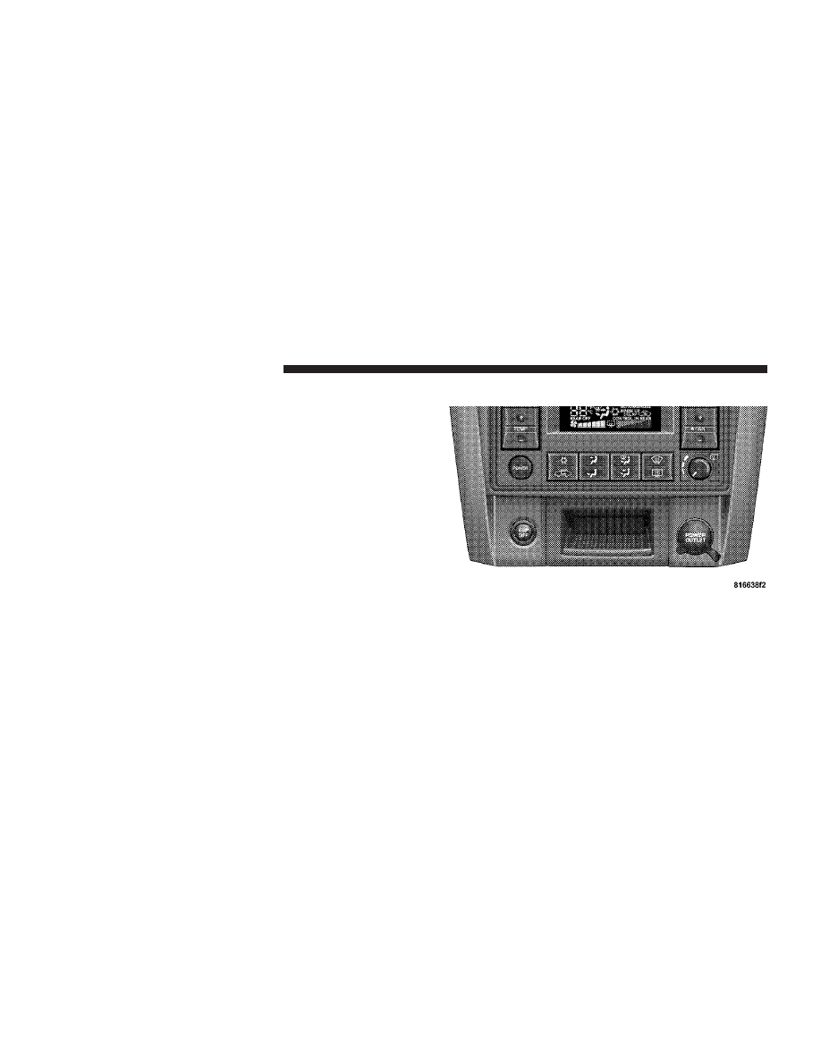
ESP OFF Switch Location

300

STARTING AND OPERATING

-------------------------------------------------------------------------------------------------------------------------------------------------------------

applies optimum pressure to the brakes in emergency
braking conditions. This can help reduce braking dis-
tances. The BAS complements the ABS. Applying the
brakes very quickly results in the best BAS assistance. To
receive the benefit of the system, you must apply con-
tinuous braking pressure during the stopping sequence.
Do not reduce brake pedal pressure unless braking is no
longer desired.

Once the brake pedal is released, the BAS is deactivated.

WARNING!

• BAS cannot prevent the natural laws of physics

from acting on the vehicle, nor can it increase
braking efficiency beyond that afforded by the
condition of the vehicle brakes and tires or the
traction afforded.

• The BAS cannot prevent accidents, including

those resulting from excessive speed in turns,
following another vehicle too closely, or hydro-
planing. Only a safe, attentive, and skillful driver
can prevent accidents.

• The capabilities of a BAS-equipped vehicle must

never be exploited in a reckless or dangerous
manner which could jeopardize the user’s safety
or the safety of others.

STARTING AND OPERATING

301

5

-------------------------------------------------------------------------------------------------------------------------------------------------------------

Electronic Roll Mitigation (ERM)

This system anticipates the potential for wheel lift by
monitoring the driver’s steering wheel input and the
speed of the vehicle. When ERM determines that the rate
of change of the steering wheel angle and vehicles speed
are sufficient to potentially cause wheel lift, it applies the
appropriate brake and may reduce engine power to
lessen the chance that wheel lift will occur. ERM will only
intervene during very severe or evasive driving maneu-
vers.

ERM can only reduce the chance of wheel lift occurring
during severe or evasive driving maneuvers. It cannot
prevent wheel lift due to other factors such as road
conditions, leaving the roadway or striking objects or
other vehicles.

WARNING!

Many factors, such as vehicle loading, road condi-
tions and driving conditions, influence the chance
that wheel lift or rollover may occur.
• ERM cannot prevent all wheel lift or rollovers,

especially those that involve leaving the roadway
or striking objects or other vehicles. Only a safe,
attentive, and skillful driver can prevent accidents.

• The capabilities of an ERM-equipped vehicle

must never be exploited in a reckless or dangerous
manner which could jeopardize the user’s safety
or the safety of others.

302

STARTING AND OPERATING

-------------------------------------------------------------------------------------------------------------------------------------------------------------

Electronic Stability Program (ESP)

This system enhances directional control and stability of
the vehicle under various driving conditions. ESP cor-
rects for over/under steering of the vehicle by applying
the brake of the appropriate wheel to assist in counter-
acting the over/under steer condition. Engine power
may also be reduced to help the vehicle maintain the
desired path.

ESP uses sensors in the vehicle to determine the vehicle
path intended by the driver and compares it to the actual
path of the vehicle. When the actual path does not match
the intended path, ESP applies the brake of the appropri-
ate wheel to assist in counteracting the oversteer or
understeer condition.

• Oversteer - when the vehicle is turning more than

appropriate for the steering wheel position.

• Understeer - when the vehicle is turning less than

appropriate for the steering wheel position.

ESP/TCS Indicator Light

The ESP/TCS Indicator Light starts to flash as
soon as the tires lose traction and the TCS or
ESP system becomes active. It will also flash
once a swaying trailer is detected and the

Trailer Sway Control (TSC) system activates. If the ESP/
TCS Indicator Light begins to flash during acceleration,
ease up on the accelerator and apply as little throttle as
possible. Be sure to adapt your speed and driving to the
prevailing road conditions.

WARNING!

• ESP cannot prevent the natural laws of physics

from acting on the vehicle, nor can it increase the
traction afforded.

(Continued)

STARTING AND OPERATING

303

5

-------------------------------------------------------------------------------------------------------------------------------------------------------------

WARNING! (Continued)

• ESP cannot prevent accidents, including those

resulting from excessive speed in turns, or hydro-
planing. Only a safe, attentive, and skillful driver
can prevent accidents.

• The capabilities of an ESP-equipped vehicle must

never be exploited in a reckless or dangerous
manner which could jeopardize the user’s safety
or the safety of others.

The ESP system has two available operating modes.

4WD/4WD LOCK or 2WD Models

ON
This is the normal operating mode for ESP in 4WD LOCK
and in 2WD vehicles. Whenever the vehicle is started or
the transfer case (if equipped) is shifted from 4WD LOW
or NEUTRAL back to 4WD LOCK, the ESP system will be

in this mode. This mode should be used for almost all
driving situations. ESP should only be turned to “Partial
Off” for specific reasons as noted below.

This mode is entered by momentarily
depressing the ESP OFF Control
Switch. When in “Partial Off” mode,
the engine management portion of
ESP has been desensitized, the thresh-
olds for ESP activation are raised, and
the “ESP/TCS Indicator Light” will be
illuminated. This mode is intended to

be used if the vehicle is in deep snow, sand or gravel
conditions and more wheel spin than ESP would nor-
mally allow is required to gain traction. Trailer Sway
Control (TSC) is not available when the system is in the

9Partial Off9 mode. To turn ESP on again, momentarily
depress the ESP OFF Control Switch. This will restore the
normal ON mode of operation. ESP always operates
under braking, even with the switch in the OFF position.

Partial Off

304

STARTING AND OPERATING

-------------------------------------------------------------------------------------------------------------------------------------------------------------

WARNING!

In the “Partial Off” mode, the engine torque reduc-
tion and stability features are desensitized. There-
fore, the enhanced vehicle stability offered by ESP is
unavailable.

NOTE:

To improve the vehicle’s traction when driving

with snow chains, or starting off in deep snow, sand or
gravel, it may be desirable to switch to the “Partial Off”
mode by pressing the ESP Control Switch. Once the
situation requiring ESP to be switched to the “Partial Off”
mode is overcome, turn ESP on by momentarily depress-
ing the ESP Control Switch. This may be done with the
vehicle in motion.

4WD LOW Range

Partial Off
This is the normal operating mode for ESP in 4WD LOW.
Whenever the vehicle is started in 4WD LOW or the
transfer case (if equipped) is shifted from 4WD LOCK or
NEUTRAL to 4WD LOW, the ESP system will be in this
mode. In 4WD LOW, ESP function is desensitized until
the vehicle reaches a speed of 30 mph (48 km/h). At 30
mph (48 km/h) the normal ESP stability function returns
and the ESP/TCS Indicator Light turns off. When the
vehicle speed drops below 25 mph (40 km/h) the ESP
system goes back to Partial Off. ESP is desensitized at low
vehicle speeds in 4WD LOW so that it will not interfere
with off road driving but ESP function returns to provide
the stability feature at speeds above 30 mph (48 km/h).
The ABS is in a special Off Road mode that allows wheels
to lock at lower speeds if gravel is detected to shorten
stopping distances.

STARTING AND OPERATING

305

5

-------------------------------------------------------------------------------------------------------------------------------------------------------------

NOTE:

When the vehicle is in 4WD LOW, a feature of

the ESP system remains active whether the ESP is on or
off. This feature functions similar to a limited slip differ-
ential and controls the wheel spin across an axle. If one
wheel on an axle is spinning faster than the other, the
system will apply the brake of the spinning wheel and
allow more engine torque to be applied to the wheel that
is not spinning.

WARNING!

In the Partial Off mode, the engine torque reduction
and stability features are desensitized. Therefore, the
enhanced vehicle stability offered by ESP is
unavailable.

Trailer Sway Control (TSC)

TSC uses sensors in the vehicle to recognize a swaying
trailer and will take the appropriate actions to attempt to
stop the sway. The system will reduce engine power and

apply individual brakes that will counter act the sway of
the trailer. TSC will become active automatically once the
swaying trailer is recognized. No driver action is re-
quired. TSC cannot stop all trailers from swaying. Al-
ways use caution when towing a trailer and follow the
tongue weight recommendations. For additional infor-
mation on towing a trailer with your vehicle, refer to

9Trailer Towing9 in Section 5.

ESP/BAS Warning Light and ESP/TCS Indicator
Light

The malfunction indicator for the ESP is combined with
the BAS indicator. The yellow ESP/BAS Warning Light
and the yellow ESP/TCS Indicator Light in the instru-
ment cluster both come on when the ignition switch is
turned to the ON position. They should both go out with
the engine running. If the ESP/BAS Warning Light comes
on continuously with the engine running, a malfunction
has been detected in either the ESP or BAS system, or
both. If this light remains on after several ignition cycles,

306

STARTING AND OPERATING

-------------------------------------------------------------------------------------------------------------------------------------------------------------

and the vehicle has been driven several miles at speeds
greater than 30 mph (48 km/h), see your authorized
dealer as soon as possible to have the problem diagnosed
and corrected.

NOTE:

• The ESP Indicator Light and the ESP/BAS Warning

Light come on momentarily each time the ignition
switch is turned ON.

• Each time the ignition is turned ON, the ESP System

will be ON even if it was turned off previously.

• The ESP Control System will make buzzing or clicking

sounds when it is active. This is normal; the sounds
will stop when ESP becomes inactive following the
maneuver that caused the ESP activation.

TIRE SAFETY INFORMATION

Tire Markings

1 — U.S. DOT Safety Stan-

dards Code (TIN)

4 — Maximum Load

2 — Size Designation

5 — Maximum Pressure

3 — Service Description

6 — Treadwear, Traction and

Temperature Grades

STARTING AND OPERATING

307

5

-------------------------------------------------------------------------------------------------------------------------------------------------------------

NOTE:

• P (Passenger) - Metric tire sizing is based on U.S.

design standards. P-Metric tires have the letter “P”
molded into the sidewall preceding the size designa-
tion. Example: P215/65R15 95H.

• European-Metric tire sizing is based on European

design standards. Tires designed to this standard have
the tire size molded into the sidewall beginning with
the section width. The letter

9P9 is absent from this tire

size designation. Example: 215/65R15 96H.

• LT (Light Truck) - Metric tire sizing is based on U.S.

design standards. The size designation for LT-Metric

tires is the same as for P-Metric tires except for the
letters “LT” that are molded into the sidewall preced-
ing the size designation. Example: LT235/85R16.

• Temporary spare tires are high-pressure compact

spares designed for temporary emergency use only.
Tires designed to this standard have the letter “T”
molded into the sidewall preceding the size designa-
tion. Example: T145/80D18 103M.

• High flotation tire sizing is based on U.S. design

standards, and it begins with the tire diameter molded
into the sidewall. Example: 31x10.5 R15 LT.

308

STARTING AND OPERATING

-------------------------------------------------------------------------------------------------------------------------------------------------------------

Tire Sizing Chart

EXAMPLE:

Size Designation:

P

= Passenger Car tire size based on U.S. design standards

(....blank....( = Passenger Car tire based on European design standards
LT

= Light Truck tire based on U.S. design standards

T

= Temporary spare tire

31

= Overall diameter in inches (in)

215

= Section width in millimeters (mm)

65

= Aspect ratio in percent (%)

— Ratio of section height to section width of tire

10.5

= Section width in inches (in)

R

= Construction code

9R9 means radial construction

9D9 means diagonal or bias construction

15

= Rim diameter in inches (in)

STARTING AND OPERATING

309

5

-------------------------------------------------------------------------------------------------------------------------------------------------------------

EXAMPLE:

Service Description:

95

= Load Index

— A numerical code associated with the maximum load a tire can carry

H

= Speed Symbol

— A symbol indicating the range of speeds at which a tire can carry a load corresponding to
its load index under certain operating conditions
— The maximum speed corresponding to the speed symbol should only be achieved under
specified operating conditions (i.e., tire pressure, vehicle loading, road conditions, and
posted speed limits)

Load Identification:

(....blank....( = Absence of any text on the sidewall of the tire indicates a Standard Load (SL) Tire
Extra Load (XL)

= Extra load (or reinforced) tire

Light Load

= Light load tire

C, D, E

= Load range associated with the maximum load a tire can carry at a specified pressure

Maximum Load

— Maximum load indicates the maximum load this tire is designed to carry

Maximum Pressure

— Maximum pressure indicates the maximum permissible cold tire inflation pressure for this

tire

310

STARTING AND OPERATING

-------------------------------------------------------------------------------------------------------------------------------------------------------------

Tire Identification Number (TIN)

The TIN may be found on one or both sides of the tire,
however, the date code may only be on one side. Tires
with white sidewalls will have the full TIN, including the
date code, located on the white sidewall side of the tire.

Look for the TIN on the outboard side of black sidewall
tires as mounted on the vehicle. If the TIN is not found on
the outboard side, then you will find it on the inboard
side of the tire.

EXAMPLE:

DOT MA L9 ABCD 0301

DOT

= Department of Transportation

— This symbol certifies that the tire is in compliance with the U.S. Department of Transportation tire
safety standards, and is approved for highway use

MA

= Code representing the tire manufacturing location (two digits)

L9

= Code representing the tire size (two digits)

ABCD

= Code used by the tire manufacturer (one to four digits)

03

= Number representing the week in which the tire was manufactured (two digits)

—03 means the 3rd week.

01

= Number representing the year in which the tire was manufactured (two digits)

—01 means the year 2001
— Prior to July 2000, tire manufacturers were only required to have one number to represent the year
in which the tire was manufactured. Example: 031 could represent the 3rd week of 1981 or 1991

STARTING AND OPERATING

311

5

-------------------------------------------------------------------------------------------------------------------------------------------------------------

Tire Loading and Tire Pressure

Tire Placard Location

NOTE:

The proper cold tire inflation pressure is listed

on either the face of the driver’s door or the driver’s side
B-Pillar.

Tire and Loading Information Placard

This placard tells you important information about
the:
1) number of people that can be carried in the vehicle
2) total weight your vehicle can carry
3) tire size designed for your vehicle
4) cold tire inflation pressures for the front, rear, and
spare tires.

Loading
The vehicle maximum load on the tire must not exceed
the load carrying capacity of the tire on your vehicle. You
will not exceed the tire’s load carrying capacity if you
adhere to the loading conditions, tire size, and cold tire
inflation pressures specified on the Tire and Loading
Information placard and in the “Vehicle Loading” section
of this manual.

Tire and Loading Information Placard

312

STARTING AND OPERATING

-------------------------------------------------------------------------------------------------------------------------------------------------------------

NOTE:

Under a maximum loaded vehicle condition,

gross axle weight ratings (GAWRs) for the front and rear
axles must not be exceeded. For further information on
GAWRs, vehicle loading, and trailer towing, refer to
“Vehicle Loading” in this section.

To determine the maximum loading conditions of your
vehicle, locate the statement “The combined weight of
occupants and cargo should never exceed XXX kg or XXX
lbs.” on the Tire and Loading Information placard. The
combined weight of occupants, cargo/luggage and
trailer tongue weight (if applicable) should never exceed
the weight referenced here.

Steps for Determining Correct Load Limit

1. Locate the statement “The combined weight of occu-
pants and cargo should never exceed XXX kg or XXX lbs”
on your vehicle’s placard.

2. Determine the combined weight of the driver and
passengers that will be riding in your vehicle.

3. Subtract the combined weight of the driver and pas-
sengers from XXX kg or XXX lbs.

4. The resulting figure equals the available amount of
cargo and luggage load capacity. For example, if “XXX”
amount equals 1,400 lbs (635 kg) and there will be five
150 lb (68 kg) passengers in your vehicle, the amount of
available cargo and luggage load capacity is 650 lbs (295
kg) (since 5 x 150 = 750, and 1400 – 750 = 650 lbs [295 kg]).

5. Determine the combined weight of luggage and cargo
being loaded on the vehicle. That weight may not safely
exceed the available cargo and luggage load capacity
calculated in Step 4.

STARTING AND OPERATING

313

5

-------------------------------------------------------------------------------------------------------------------------------------------------------------

6. If your vehicle will be towing a trailer, load from your
trailer will be transferred to your vehicle. Consult this
manual to determine how this reduces the available
cargo and luggage load capacity of your vehicle.

NOTE:

The following table shows examples on how to

calculate total load, cargo/luggage, and towing capaci-
ties of your vehicle with varying seating configurations

and number and size of occupants. This table is for
illustration purposes only and may not be accurate for
the seating and load carry capacity of your vehicle.

NOTE:

For the following example, the combined weight

of occupants and cargo should never exceed 865 lbs (392
kg).

314

STARTING AND OPERATING

-------------------------------------------------------------------------------------------------------------------------------------------------------------

STARTING AND OPERATING

315

5

-------------------------------------------------------------------------------------------------------------------------------------------------------------


Content      ..     17      18      19      20     ..