Chrysler Town, Dodge Caravan. Manual - part 975


  Index      Chrysler     Chrysler TOWN & COUNTRY, VOYAGER, Dodge Caravan - service repair manual 2001-2007 year


Search            


Content   ..  973  974  975  976   ..


Chrysler Town, Dodge Caravan. Manual - part 975


11.2

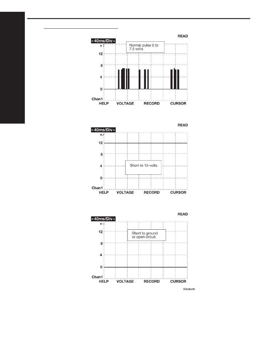
PCI BUS LAB SCOPE PATTERN

C

H

A
R

T
S

A

N

D

G

R
A

P

H

S

1136

CHARTS AND GRAPHS

TABLE OF CONTENTS

1.0

INTRODUCTION . . . . . . . . . . . . . . . . . . . . . . . . . . . . . . . . . . . . . . . . . . . . . . . . . . . . . . . . .1

1.1

SYSTEM COVERAGE . . . . . . . . . . . . . . . . . . . . . . . . . . . . . . . . . . . . . . . . . . . . . . .1

1.2

SIX-STEP TROUBLESHOOTING PROCEDURE . . . . . . . . . . . . . . . . . . . . . . . . . .1

2.0

IDENTIFICATION OF SYSTEM . . . . . . . . . . . . . . . . . . . . . . . . . . . . . . . . . . . . . . . . . . . . .1

3.0

SYSTEM DESCRIPTION AND FUNCTIONAL OPERATION . . . . . . . . . . . . . . . . . . . . . .1

3.1

TEVES MARK 20e SYSTEM DESCRIPTION . . . . . . . . . . . . . . . . . . . . . . . . . . . . .1

3.2

TRACTION CONTROL SYSTEM (TCS) DESCRIPTION (IF EQUIPPED) . . . . . . .1

3.3

SYSTEM COMPONENTS . . . . . . . . . . . . . . . . . . . . . . . . . . . . . . . . . . . . . . . . . . . . .2

3.3.1

ABS AND BRAKE WARNING INDICATORS . . . . . . . . . . . . . . . . . . . . . .2

3.3.2

CONTROLLER ANTILOCK BRAKE (CAB) . . . . . . . . . . . . . . . . . . . . . . .2

3.3.3

HYDRAULIC CONTROL UNIT . . . . . . . . . . . . . . . . . . . . . . . . . . . . . . . . .2

3.3.4

ABS SWITCHES/SENSORS. . . . . . . . . . . . . . . . . . . . . . . . . . . . . . . . . . .3

3.3.5

ABS INITIALIZATION . . . . . . . . . . . . . . . . . . . . . . . . . . . . . . . . . . . . . . . .3

3.3.6

ABS DIAGNOSTIC MODE . . . . . . . . . . . . . . . . . . . . . . . . . . . . . . . . . . . .3

3.3.7

TRACTION CONTROL OPERATION (IF EQUIPPED) . . . . . . . . . . . . . .4

3.5

DIAGNOSTIC TROUBLE CODES . . . . . . . . . . . . . . . . . . . . . . . . . . . . . . . . . . . . . .4

3.6

FREEZE FRAME . . . . . . . . . . . . . . . . . . . . . . . . . . . . . . . . . . . . . . . . . . . . . . . . . . . .4

3.7

TIRE PRESSURE MONITORING SYSTEM . . . . . . . . . . . . . . . . . . . . . . . . . . . . . .4

3.7.1

TRAINING THE EVIC . . . . . . . . . . . . . . . . . . . . . . . . . . . . . . . . . . . . . . . .4

3.7.2

PRESSURE THRESHOLDS . . . . . . . . . . . . . . . . . . . . . . . . . . . . . . . . . . .5

3.7.2.1 CRITICAL AND NON-CRITICAL SYSTEM ALERTS . . . . . . . . . . . . . . . .5
3.7.3

SYSTEM FAULTS . . . . . . . . . . . . . . . . . . . . . . . . . . . . . . . . . . . . . . . . . . .5

3.7.4

SPARE WHEEL AUTO-DETECT . . . . . . . . . . . . . . . . . . . . . . . . . . . . . . .5

3.7.5

DIAGNOSING AND CLEARING SYSTEM FAULTS . . . . . . . . . . . . . . . .6

3.7.6

SYSTEM TEST . . . . . . . . . . . . . . . . . . . . . . . . . . . . . . . . . . . . . . . . . . . . .6

3.8

DRBIII

T

ERROR MESSAGES AND BLANK SCREEN . . . . . . . . . . . . . . . . . . . . . .6

3.8.1

DRBIII

T

DOES NOT POWER UP. . . . . . . . . . . . . . . . . . . . . . . . . . . . . . .6

3.8.2

DISPLAY IS NOT VISIBLE . . . . . . . . . . . . . . . . . . . . . . . . . . . . . . . . . . . .6

4.0

DISCLAIMERS, SAFETY, WARNINGS . . . . . . . . . . . . . . . . . . . . . . . . . . . . . . . . . . . . . . .7

4.1

DISCLAIMERS. . . . . . . . . . . . . . . . . . . . . . . . . . . . . . . . . . . . . . . . . . . . . . . . . . . . . .7

4.2

SAFETY . . . . . . . . . . . . . . . . . . . . . . . . . . . . . . . . . . . . . . . . . . . . . . . . . . . . . . . . . . .7

4.2.1

TECHNICIAN SAFETY INFORMATION . . . . . . . . . . . . . . . . . . . . . . . . . .7

4.2.2

VEHICLE PREPARATION FOR TESTING . . . . . . . . . . . . . . . . . . . . . . . .7

4.2.3

SERVICING SUB-ASSEMBLIES . . . . . . . . . . . . . . . . . . . . . . . . . . . . . . .7

4.2.4

DRBIII

T

SAFETY INFORMATION . . . . . . . . . . . . . . . . . . . . . . . . . . . . . .7

4.3

WARNINGS . . . . . . . . . . . . . . . . . . . . . . . . . . . . . . . . . . . . . . . . . . . . . . . . . . . . . . . .8

4.3.1

VEHICLE DAMAGE WARNINGS . . . . . . . . . . . . . . . . . . . . . . . . . . . . . . .8

4.3.2

ROAD TESTING A COMPLAINT VEHICLE . . . . . . . . . . . . . . . . . . . . . . .8

4.4

DIAGNOSIS . . . . . . . . . . . . . . . . . . . . . . . . . . . . . . . . . . . . . . . . . . . . . . . . . . . . . . . .8

5.0

REQUIRED TOOLS AND EQUIPMENT . . . . . . . . . . . . . . . . . . . . . . . . . . . . . . . . . . . . . .8

6.0

GLOSSARY OF TERMS. . . . . . . . . . . . . . . . . . . . . . . . . . . . . . . . . . . . . . . . . . . . . . . . . . .9

7.0

DIAGNOSTIC INFORMATION AND PROCEDURES . . . . . . . . . . . . . . . . . . . . . . . . . . .11

BRAKES (CAB)
BUS SYSTEM COMMUNICATION FAILURE 
. . . . . . . . . . . . . . . . . . . . . . . . . . . . . . . . .12

i

TABLE OF CONTENTS - Continued

CAB INTERNAL FAILURE . . . . . . . . . . . . . . . . . . . . . . . . . . . . . . . . . . . . . . . . . . . . . . . .14
CLUSTER LAMP FAILURE. . . . . . . . . . . . . . . . . . . . . . . . . . . . . . . . . . . . . . . . . . . . . . . .16
INCORRECT TONE WHEEL FAILURE . . . . . . . . . . . . . . . . . . . . . . . . . . . . . . . . . . . . . .18
LEFT FRONT SENSOR CIRCUIT FAILURE . . . . . . . . . . . . . . . . . . . . . . . . . . . . . . . . . .19
LEFT REAR SENSOR CIRCUIT FAILURE . . . . . . . . . . . . . . . . . . . . . . . . . . . . . . . . . . .19
RIGHT FRONT SENSOR CIRCUIT FAILURE . . . . . . . . . . . . . . . . . . . . . . . . . . . . . . . . .19
RIGHT REAR SENSOR CIRCUIT FAILURE . . . . . . . . . . . . . . . . . . . . . . . . . . . . . . . . . .19
LEFT FRONT WHEEL SPEED SIGNAL FAILURE . . . . . . . . . . . . . . . . . . . . . . . . . . . . .24
LEFT REAR WHEEL SPEED SIGNAL FAILURE . . . . . . . . . . . . . . . . . . . . . . . . . . . . . .24
RIGHT FRONT WHEEL SPEED SIGNAL FAILURE . . . . . . . . . . . . . . . . . . . . . . . . . . . .24
RIGHT REAR WHEEL SPEED SIGNAL FAILURE . . . . . . . . . . . . . . . . . . . . . . . . . . . . .24
PUMP CIRCUIT FAILURE . . . . . . . . . . . . . . . . . . . . . . . . . . . . . . . . . . . . . . . . . . . . . . . .27
SYSTEM OVER VOLTAGE. . . . . . . . . . . . . . . . . . . . . . . . . . . . . . . . . . . . . . . . . . . . . . . .31
SYSTEM UNDER VOLTAGE . . . . . . . . . . . . . . . . . . . . . . . . . . . . . . . . . . . . . . . . . . . . . .34
VALVE POWER FEED FAILURE . . . . . . . . . . . . . . . . . . . . . . . . . . . . . . . . . . . . . . . . . . .36
*BRAKE LAMP SWITCH INOPERATIVE . . . . . . . . . . . . . . . . . . . . . . . . . . . . . . . . . . . . .39
*TRAC OFF INDICATOR NEVER/ALWAYS ON . . . . . . . . . . . . . . . . . . . . . . . . . . . . . . .40
*TRAC ON INDICATOR NEVER/ALWAYS ON . . . . . . . . . . . . . . . . . . . . . . . . . . . . . . . .43

COMMUNICATION
*NO RESPONSE FROM CONTROLLER ANTILOCK BRAKE 
. . . . . . . . . . . . . . . . . . . .44

VERIFICATION TESTS
VERIFICATION TESTS 
. . . . . . . . . . . . . . . . . . . . . . . . . . . . . . . . . . . . . . . . . . . . . . . . . . .46

8.0

COMPONENT LOCATIONS . . . . . . . . . . . . . . . . . . . . . . . . . . . . . . . . . . . . . . . . . . . . . . .47

8.1

CONTROLLER ANTILOCK BRAKE (CAB) . . . . . . . . . . . . . . . . . . . . . . . . . . . . . .47

8.2

DATA LINK CONNECTOR . . . . . . . . . . . . . . . . . . . . . . . . . . . . . . . . . . . . . . . . . . .47

8.3

FUSES . . . . . . . . . . . . . . . . . . . . . . . . . . . . . . . . . . . . . . . . . . . . . . . . . . . . . . . . . . .47

8.4

TRACTION CONTROL SWITCH . . . . . . . . . . . . . . . . . . . . . . . . . . . . . . . . . . . . . .48

8.4.1

TRACTION CONTROL INDICATORS . . . . . . . . . . . . . . . . . . . . . . . . . .48

8.5

WHEEL SPEED SENSORS . . . . . . . . . . . . . . . . . . . . . . . . . . . . . . . . . . . . . . . . . .48

8.5.1

FRONT. . . . . . . . . . . . . . . . . . . . . . . . . . . . . . . . . . . . . . . . . . . . . . . . . . .48

8.5.2

REAR . . . . . . . . . . . . . . . . . . . . . . . . . . . . . . . . . . . . . . . . . . . . . . . . . . . .49

8.5A WHEEL SPEED SENSOR CONNECTORS. . . . . . . . . . . . . . . . . . . . . . . . . . . . . .49

8.5A.1 FRONT. . . . . . . . . . . . . . . . . . . . . . . . . . . . . . . . . . . . . . . . . . . . . . . . . . .49
8.5A.2 REAR . . . . . . . . . . . . . . . . . . . . . . . . . . . . . . . . . . . . . . . . . . . . . . . . . . . .49

8.6

BRAKE LAMP SWITCH . . . . . . . . . . . . . . . . . . . . . . . . . . . . . . . . . . . . . . . . . . . . .50

9.0

CONNECTOR PINOUTS . . . . . . . . . . . . . . . . . . . . . . . . . . . . . . . . . . . . . . . . . . . . . . . . .51

ABS PUMP MOTOR . . . . . . . . . . . . . . . . . . . . . . . . . . . . . . . . . . . . . . . . . . . . . . . . . . . . .51
BRAKE LAMP SWITCH . . . . . . . . . . . . . . . . . . . . . . . . . . . . . . . . . . . . . . . . . . . . . . . . . .51
CONTROLLER ANTILOCK BRAKE . . . . . . . . . . . . . . . . . . . . . . . . . . . . . . . . . . . . . . . . .52
LEFT FRONT WHEEL SPEED SENSOR . . . . . . . . . . . . . . . . . . . . . . . . . . . . . . . . . . . .52
LEFT REAR WHEEL SPEED SENSOR. . . . . . . . . . . . . . . . . . . . . . . . . . . . . . . . . . . . . .52
RIGHT FRONT WHEEL SPEED SENSOR . . . . . . . . . . . . . . . . . . . . . . . . . . . . . . . . . . .53
RIGHT REAR WHEEL SPEED SENSOR . . . . . . . . . . . . . . . . . . . . . . . . . . . . . . . . . . . .53
TRACTION CONTROL SWITCH . . . . . . . . . . . . . . . . . . . . . . . . . . . . . . . . . . . . . . . . . . .53

10.0

SCHEMATIC DIAGRAMS. . . . . . . . . . . . . . . . . . . . . . . . . . . . . . . . . . . . . . . . . . . . . . . . .55

10.1 TEVES MARK 20E ANTILOCK BRAKE SYSTEM – ABS . . . . . . . . . . . . . . . . . . .55

ii

1.0

INTRODUCTION

The procedures contained in this manual include

all the specifications, instructions, and graphics
needed to diagnose the 2003 Chrysler Town &
Country, Dodge Caravan, and Chrysler Voyager
Mark 20e Antilock Braking System (ABS), and
Mark 20e Antilocke Braking System with Traction
Control. The diagnostics in this manual are based
on the failure condition or symptom being present
at time of diagnosis.

Please follow the recommendations below when

choosing your diagnostic path.

1. First make sure the DRBIII

t is communicating

with the CAB. If the DRBIII

t displays a “No

Response” condition, you must diagnose that
first.

2. Read DTC’s (diagnostic trouble codes) with the

DRBIII

t.

3. If no DTC’s are present, identify the customer

complaint.

4. Once the DTC or customer complaint is identi-

fied, locate the matching test in the Table of
Contents and begin to diagnose the symptom.

All component location views are in Section 8.0.

All connector pinouts are in Section 9.0. All sche-
matics are in Section 10.0.

An asterisk (*) placed before the symptom de-

scription indicates a concern with no associated
DTC.

When repairs are required, refer to the appropri-

ate service manual for the proper removal and
repair procedure.

Diagnostic procedures change every year. New

diagnostic systems may be added; carry over sys-
tems may be enhanced. READ THIS MANUAL
BEFORE TRYING TO DIAGNOSE A VEHICLE
CODE. It is recommended that you review the
entire manual to become familiar with all new and
changed diagnostic procedures.

After using this book, if you have any comments

or recommendations, please fill out the form at the
back of the book and mail it back to us.

1.1

SYSTEM COVERAGE

This diagnostic procedure manual covers the an-

tilock braking system (ABS), and the traction con-
trol system found on: Chrysler Town and Country,
Dodge Caravan, and Chrysler Voyager.

1.2

SIX-STEP TROUBLESHOOTING
PROCEDURE

Diagnosis of the controller antilock brake module

is done in six basic steps:

verification of complaint

verification of any related symptoms

symptom analysis

problem isolation

repair of isolated problem

verification of proper operation

2.0

IDENTIFICATION OF
SYSTEM

Vehicles equipped with the Teves Mark 20e an-

tilock brake system can be identified by the pres-
ence of the controller antilock brake module located
beneath the master cylinder.

The presence of the Traction Control system is

indicated by the TRAC OFF switch on top of the
steering column shroud.

3.0

SYSTEM DESCRIPTION AND
FUNCTIONAL OPERATION

3.1

TEVES MARK 20e SYSTEM
DESCRIPTION

The controller antilock brake module is used to

monitor wheel speeds and to modulate (control)
hydraulic pressure in each brake channel. The
modulated hydraulic pressure is used to prevent
wheel lock-up during braking.

The Teves Mark 20e system uses a diagonal split

hydraulic brake system. In the standard brake
mode the master cylinder primary circuit supplies
pressure to the right front and left rear wheel
brakes, and the secondary master cylinder circuit
supplies pressure to the left front and right rear
wheel brakes.

All vehicles equipped with ABS use Electronic

Variable Brake Proportioning (EVPB) to balance
front-to-rear braking when brakes are applied in
the partial braking range.

3.2

TRACTION CONTROL SYSTEM (TCS)
DESCRIPTION (IF EQUIPPED)

The main purpose of traction control is to reduce

wheel slip and maintain traction at the driven
wheels when road surfaces are slippery. The trac-
tion control system reduces wheel slip by braking
the wheel that is losing traction. The system is
designed to operate at speeds below 56 km/h (35
mph).

1

GENERAL INFORMATION


Content   ..  973  974  975  976   ..