Chrysler Town, Dodge Caravan. Manual - part 754
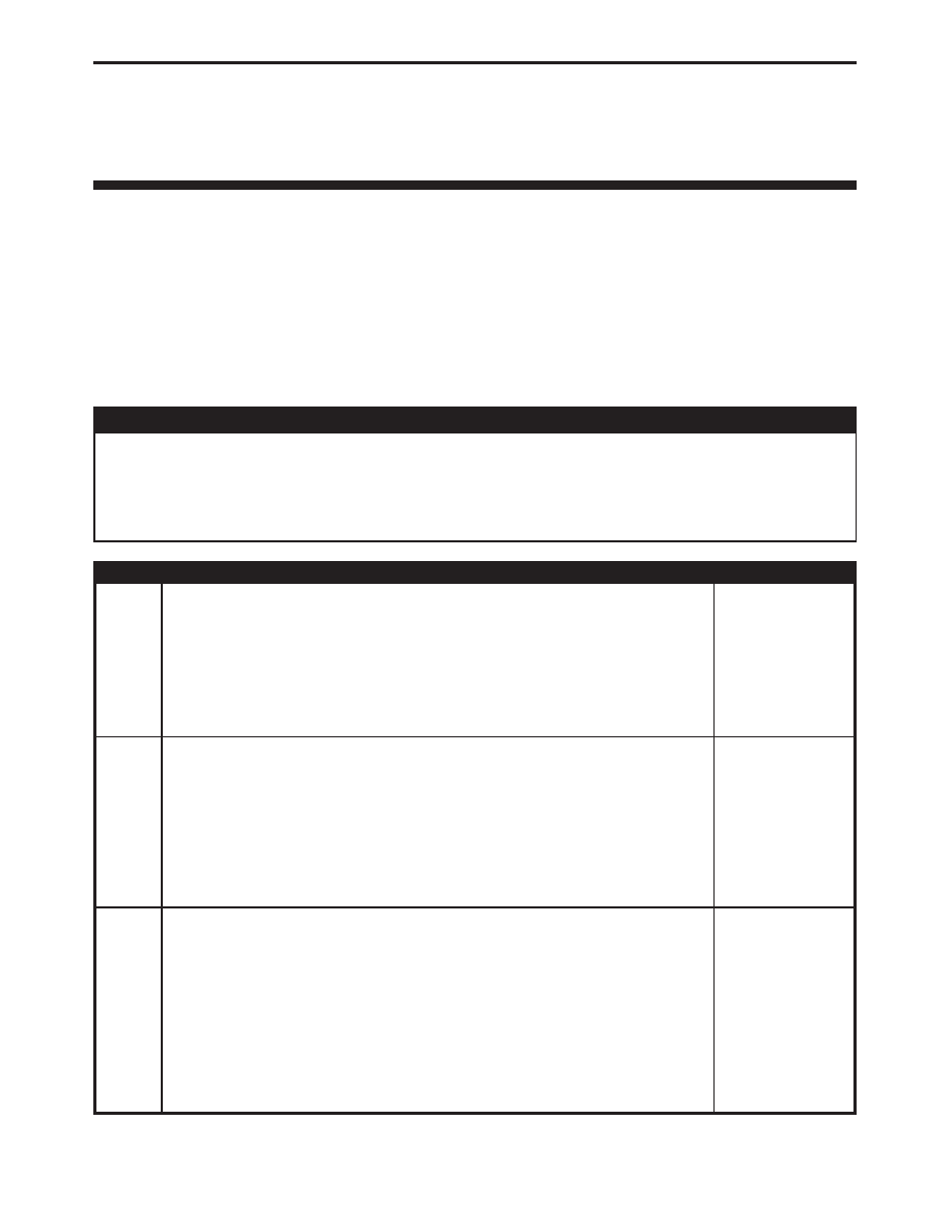
Symptom:
REAR MODE DOOR TRAVEL TOO LARGE (ACTIVE)
When Monitored and Set Condition:
REAR MODE DOOR TRAVEL TOO LARGE (ACTIVE)
When Monitored:
With the ignition on and the IOD fuse installed.
Set Condition:
This DTC is set when the ATC monitors the travel range during system
initialization and the measured range is greater than expected.
POSSIBLE CAUSES
CHECK THE ATC FOR DTCS
REAR MODE DOOR ACTUATOR
REAR MODE DOOR LINKAGE
ATC
TEST
ACTION
APPLICABILITY
1
Turn the ignition on.
With the DRB, read the active ATC DTCs.
Is the REAR MODE DOOR NOT RESPONDING DTC set?
All
Yes
→ Return to the symptom list and choose the symptom.
With the DRBIII
t, reset the ATC after repair is complete.
Perform BODY VERIFICATION TEST - VER 1.
No
→ Go To 2
2
Turn the ignition off.
Remove the Rear Mode Door Actuator.
By hand, attempt to rotate the Rear Mode Door Actuator in both directions.
Did the mode door actuator turn in either direction?
All
Yes
→ Replace the Rear Mode Door Actuator.
With the DRBIII
t, reset the ATC after repair is complete.
Perform BODY VERIFICATION TEST - VER 1.
No
→ Go To 3
3
Remove the Rear Mode Door Actuator. Rotate the mode door (door only). Note: This
should rotate approximately 45 degrees from stop to stop.
Inspect the rear mode door linkage for excessive wear or missing linkage.
Were any mechanical problems found?
All
Yes
→ Repair or replace the rear mode door/linkage as necessary.
With the DRBIII
t, reset the ATC after repair is complete.
Perform BODY VERIFICATION TEST - VER 1.
No
→ Replace the ATC.
With the DRBIII
t, reset the ATC after repair is complete.
Perform BODY VERIFICATION TEST - VER 1.
252
AUTOMATIC TEMPERATURE CONTROL