Chrysler Town, Dodge Caravan. Manual - part 550


  Index      Chrysler     Chrysler TOWN & COUNTRY, VOYAGER, Dodge Caravan - service repair manual 2001-2007 year


Search            


Content   ..  548  549  550  551   ..


Chrysler Town, Dodge Caravan. Manual - part 550


2. Purge Flow:

The above rationality check is considered suffi-

cient to confirm purge solenoid function and con-
formance with the purge flow test requirement. The
Purge Flow Monitor is passed based on switch
activity when purge is turned on or based on a rich
fuel control shift when purge is turned on.

Medium and Large Leak Test (Intrusive)

NOTE: This intrusive test will only be run if
the Small Leak (passive) test fails, or is
inconclusive (the switch does not close)

Enabling Conditions:

40 °F to 90 °F

Engine temperature at startup within 10 °F of
the ambient temperature

Fuel level less than 85%

The intrusive Medium and Large leak are con-

ducted as follows:

De-energize the NVLD solenoid to seal the can-
ister vent.

Activate purge shortly after closed loop. Pull the
tank vacuum past the vacuum switch point (1

9

H2O vacuum) of the NVLD for a specific time
while tracking the standard purge flow rate.

Turn purge off and determine how long it takes to
decay the tank vacuum and reopen the switch.
Determine the leak size from the time it took to
reopen the switch. Note: Fuel level is an impor-
tant determining factor.

If the switch does not close, a more aggressive
purge flow will be applied to determine if it is a
very large leak, missing fuel cap, problem with
the NVLD device, purge flow problem, etc...
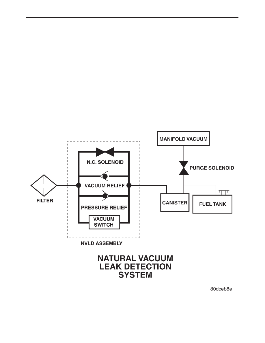
FIGURE 1

8

GENERAL INFORMATION

FIGURE 2

9

GENERAL INFORMATION

LEAK DETECTION PUMP SYSTEM — IF
EQUIPPED

The evaporative emission system is designed to

prevent the escape of fuel vapors from the fuel
system. Leaks in the system, even small ones, can
allow fuel vapors to escape into the atmosphere.
Government regulations require onboard testing to
make sure that the evaporative (EVAP) system is
functioning properly. The leak detection system
tests for EVAP system leaks and blockage. It also
performs self-diagnostics. During self-diagnostics,
the Powertrain Control Module (PCM) first checks
the Leak Detection Pump (LDP) for electrical and
mechanical faults. If the first checks pass, the PCM
then uses the LDP to seal the vent valve and pump
air into the system to pressurize it. If a leak is
present, the PCM will continue pumping the LDP to
replace the air that leaks out. The PCM determines
the size of the leak based on how fast/long it must
pump the LDP as it tries to maintain pressure in
the system.

EVAP LEAK DETECTION SYSTEM COMPONENTS
(FIGURE 1)

Service Port: Used with special tools like the

Miller

Evaporative

Emissions

Leak

Detector

(EELD) to test for leaks in the system.

EVAP Purge Solenoid: The PCM uses the

EVAP purge solenoid to control purging of excess
fuel vapors stored in the EVAP canister. It remains
closed during leak testing to prevent loss of pres-
sure.

EVAP Canister: The EVAP canister stores fuel

vapors from the fuel tank for purging.

EVAP Purge Orifice: Limits purge volume.
EVAP System Air Filter: Provides air to the

LDP for pressurizing the system. It filters out dirt
while allowing a vent to atmosphere for the EVAP
system.

Leak Detection Pump (LDP) Components:

The main purpose of the LDP is to pressurize the

fuel system for leak checking. It closes the EVAP
system vent to atmospheric pressure so the system
can be pressurized for leak testing. The diaphragm
is powered by engine vacuum. It pumps air into the
EVAP system to develop a pressure of about 7.5

9

H

2

O (

1

4

) psi. A reed switch in the LDP allows the

PCM to monitor the position of the LDP diaphragm.
The PCM uses the reed switch input to monitor how
fast the LDP is pumping air into the EVAP system.
This allows detection of leaks and blockage.

The LDP assembly consists of several parts (Fig-

ure 2). The solenoid is controlled by the PCM, and it
connects the upper pump cavity to either engine
vacuum or atmospheric pressure. A vent valve
closes the EVAP system to atmosphere, sealing the
system during leak testing. The pump section of the
LDP consists of a diaphragm that moves up and
down to bring air in through the air filter and inlet
check valve, and pump it out through an outlet
check valve into the EVAP system.

The diaphragm is pulled up by engine vacuum,

and pushed down by spring pressure, as the LDP
solenoid turns on and off. The LDP also has a
magnetic reed switch to signal diaphragm position
to the PCM. When the diaphragm is down, the
switch is closed, which sends a 12 V (system volt-
age) signal to the PCM. When the diaphragm is up,
the switch is open, and there is no voltage sent to
the PCM. This allows the PCM to monitor LDP
pumping action as it turns the LDP solenoid on and
off.

LDP AT REST (NOT POWERED)

When the LDP is at rest (no electrical/vacuum)

the diaphragm is allowed to drop down if the
internal (EVAP system) pressure is not greater than
the return spring. The LDP solenoid blocks the
engine vacuum port and opens the atmospheric

FIGURE 1

FIGURE 2

10

GENERAL INFORMATION

pressure port connected through the EVAP system
air filter. The vent valve is held open by the dia-
phragm. This allows the canister to see atmospheric
pressure (Figure 3).

DIAPHRAGM UPWARD MOVEMENT

When the PCM energizes the LDP solenoid, the

solenoid blocks the atmospheric port leading
through the EVAP air filter and at the same time
opens the engine vacuum port to the pump cavity
above the diaphragm. The diaphragm moves up-
ward when the vacuum above the diaphragm ex-
ceeds spring force. This upward movement closes
the vent valve. It also causes low pressure below the
diaphragm, unseating the inlet check valve and
allowing air in from the EVAP air filter. When the
diaphragm completes its upward movement, the
LDP reed switch turns from closed to open (Figure
4).

DIAPHRAGM DOWNWARD MOVEMENT

Based on reed switch input, the PCM de-

energizes the LDP solenoid, causing it to block the
vacuum port, and open the atmospheric port. This
connects the upper pump cavity to atmosphere
through the EVAP air filter. The spring is now able
to push the diaphragm down. The downward move-
ment of the diaphragm closes the inlet check valve
and opens the outlet check valve pumping air into
the evaporative system. The LDP reed switch turns
from open to closed, allowing the PCM to monitor
LDP pumping (diaphragm up/down) activity (Fig-
ure 5). During the pumping mode, the diaphragm
will not move down far enough to open the vent
valve.

The pumping cycle is repeated as the solenoid is

turned on and off. When the evaporative system
begins to pressurize, the pressure on the bottom of
the diaphragm will begin to oppose the spring
pressure, slowing the pumping action. The PCM
watches the time from when the solenoid is de-
energized, until the diaphragm drops down far
enough for the reed switch to change from open to
closed. If the reed switch changes too quickly, a leak
may be indicated. The longer it takes the reed
switch to change state, the tighter the evaporative
system is sealed. If the system pressurizes too
quickly, a restriction somewhere in the EVAP sys-
tem may be indicated.

PUMPING ACTION

During portions of this test, the PCM uses the

reed switch to monitor diaphragm movement. The
solenoid is only turned on by the PCM after the reed
switch changes from open to closed, indicating that
the diaphragm has moved down. At other times
during the test, the PCM will rapidly cycle the LDP
solenoid on and off to quickly pressurize the system.
During rapid cycling, the diaphragm will not move
enough to change the reed switch state. In the state

FIGURE 3

FIGURE 4

FIGURE 5

11

GENERAL INFORMATION


Content   ..  548  549  550  551   ..