Chrysler Town, Dodge Caravan. Manual - part 523


  Index      Chrysler     Chrysler TOWN & COUNTRY, VOYAGER, Dodge Caravan - service repair manual 2001-2007 year


Search            


Content   ..  521  522  523  524   ..


Chrysler Town, Dodge Caravan. Manual - part 523


WARNING: REFER TO THE APPLICABLE WARN-
INGS AND CAUTIONS FOR THIS SYSTEM BEFORE
PERFORMING

THE

FOLLOWING

OPERATION.

(Refer to 24 - HEATING & AIR CONDITIONING/
PLUMBING - FRONT - WARNING - A/C PLUMBING)
and (Refer to 24 - HEATING & AIR CONDITIONING/
PLUMBING - FRONT - CAUTION - A/C PLUMBING).

(1) Position the suction line into the engine com-

partment.

(2) Remove the tape or plugs from the suction line

and liquid line fittings and both expansion valve
ports.

(3) Lubricate new rubber O-ring seals with clean

refrigerant oil and install them on the suction line
and liquid line fittings.

(4) Reconnect the liquid line and suction line fit-

tings to the expansion valve.

(5) Install and tighten the nut that secures the

suction line and liquid line fittings to the expansion
valve. Tighten the nut to 23 N·m (17 ft. lbs.).

(6) Engage the retainer that secures the suction

line routing clip to the filter-drier mounting bracket
on the side of the right front strut tower in the
engine compartment. (If Equipped).

(7) Remove the tape or plugs from the compressor

suction port and the suction line fitting.

(8) Lubricate a new rubber O-ring seal with clean

refrigerant oil and install it on the suction line fit-
ting.

(9) Install a new dual plan seal and reconnect the

suction line fitting to the compressor suction port.

(10) Install and tighten the nut that secures the

suction line fitting to the compressor. Tighten the nut
to 23 N·m (17 ft. lbs.).

(11) Reconnect the drain tube to the wiper module

drain on the right side of the engine compartment.

(12) Reinstall the air cleaner top cover and snorkel

onto the air cleaner housing located on the right side
of the engine compartment.

(13) Reconnect the battery negative cable.
(14) If the vehicle is equipped with the optional

rear air conditioner, go to Step 15. If the vehicle does
not have the optional rear air conditioner, go to Step
21.

(15) Raise and support the vehicle.
(16) Remove the tape or plugs from the suction

line extension fitting and the underbody suction line
fitting.

(17) Lubricate a new rubber O-ring seal with clean

refrigerant oil and install it on the underbody suction
line fitting.

(18) Reconnect the suction line extension fitting to

the underbody suction line fitting. Tighten the fit-
tings to 23 N·m (17 ft. lbs.).

(19) Install a new tie strap just forward of the con-

nections between the underbody plumbing and the

engine compartment plumbing for the rear heater
and air conditioner.

(20) Lower the vehicle.
(21) Evacuate the refrigerant system. (Refer to 24

- HEATING & AIR CONDITIONING/PLUMBING -
FRONT/REFRIGERANT

-

STANDARD

PROCE-

DURE - REFRIGERANT SYSTEM EVACUATE).

(22) Charge the refrigerant system. (Refer to 24 -

HEATING & AIR CONDITIONING/PLUMBING -
FRONT/REFRIGERANT

-

STANDARD

PROCE-

DURE - REFRIGERANT SYSTEM CHARGE).

SERVICE PORTS

REMOVAL

WARNING: REFER TO THE APPLICABLE WARN-
INGS AND CAUTIONS FOR THIS SYSTEM BEFORE
PERFORMING

THE

FOLLOWING

OPERATION.

(Refer to 24 - HEATING & AIR CONDITIONING/
PLUMBING - FRONT - WARNING - A/C PLUMBING)
and (Refer to 24 - HEATING & AIR CONDITIONING/
PLUMBING - FRONT - CAUTION - A/C PLUMBING).

(1) Remove the protective cap from the A/C service

port (Fig. 36).

(2) Recover the refrigerant from the refrigerant

system. (Refer to 24 - HEATING & AIR CONDI-
TIONING/PLUMBING - FRONT/REFRIGERANT -
STANDARD

PROCEDURE

-

REFRIGERANT

RECOVERY).

(3) Using a standard Schrader-type valve core tool,

remove the valve core from the A/C service port (Low

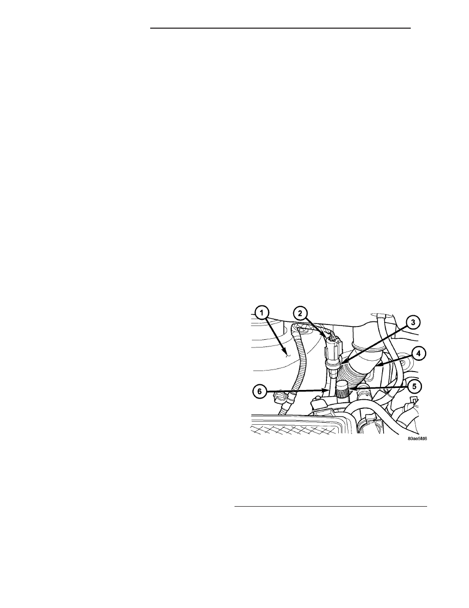
Fig. 36 A/C Service Port - Typical

1 - RIGHT FRONT STRUT TOWER
2 - CONNECTOR
3 - A/C PRESSURE TRANSDUCER
4 - RIGHT WIPER MODULE DRAIN TUBE
5 - HIGH SIDE SERVICE PORT
6 - LIQUID LINE

24 - 92

PLUMBING - FRONT

RS

SUCTION LINE (Continued)

side only). If the high side requires service replace-
ment of the line is required).

(4) Install a plug in or tape over the opened A/C

service port.

INSTALLATION

WARNING: REFER TO THE APPLICABLE WARN-
INGS AND CAUTIONS FOR THIS SYSTEM BEFORE
PERFORMING

THE

FOLLOWING

OPERATION.

(Refer to 24 - HEATING & AIR CONDITIONING/
PLUMBING - FRONT - WARNING - A/C PLUMBING)
and (Refer to 24 - HEATING & AIR CONDITIONING/
PLUMBING - FRONT - CAUTION - A/C PLUMBING).

(1) Lubricate the A/C service port valve core with

clean refrigerant oil prior to installation. Use only
refrigerant oil of the type recommended for the com-
pressor in the vehicle.

(2) Remove the tape or plug from the A/C service

port.

(3) Using a standard Schrader-type valve core tool,

install and tighten the replacement valve core into

the A/C service port (Low side only). If the high side
requires service replacement of the line assembly is
required).

CAUTION: A valve core that is not fully seated in
the A/C service port can result in damage to the
valve during refrigerant system evacuation and
charge. Such damage may result in a loss of sys-
tem refrigerant while uncoupling the charge adapt-
ers.

(4) Evacuate the refrigerant system. (Refer to 24 -

HEATING & AIR CONDITIONING/PLUMBING -
FRONT/REFRIGERANT

-

STANDARD

PROCE-

DURE - REFRIGERANT SYSTEM EVACUATE).

(5) Charge the refrigerant system. (Refer to 24 -

HEATING & AIR CONDITIONING/PLUMBING -
FRONT/REFRIGERANT

-

STANDARD

PROCE-

DURE - REFRIGERANT SYSTEM CHARGE).

(6) Reinstall the protective cap onto the A/C ser-

vice port.

RS

PLUMBING - FRONT

24 - 93

SERVICE PORTS (Continued)

PLUMBING - REAR

TABLE OF CONTENTS

page

page

EVAPORATOR

DESCRIPTION

. . . . . . . . . . . . . . . . . . . . . . . . . 94

OPERATION

. . . . . . . . . . . . . . . . . . . . . . . . . . . 94

REMOVAL

REMOVAL - REAR EVAPORATOR

. . . . . . . . . 94

REMOVAL - EVAPORATOR LINE

EXTENSION . . . . . . . . . . . . . . . . . . . . . . . . . 95

INSTALLATION

INSTALLATION - REAR EVAPORATOR

. . . . . 96

INSTALLATION - EVAPORATOR LINE

EXTENSION . . . . . . . . . . . . . . . . . . . . . . . . . 96

EXPANSION VALVE

DESCRIPTION

. . . . . . . . . . . . . . . . . . . . . . . . . 96

OPERATION

. . . . . . . . . . . . . . . . . . . . . . . . . . . 97

DIAGNOSIS AND TESTING - EXPANSION

VALVE

. . . . . . . . . . . . . . . . . . . . . . . . . . . . . . 97

REMOVAL

. . . . . . . . . . . . . . . . . . . . . . . . . . . . . 97

INSTALLATION

. . . . . . . . . . . . . . . . . . . . . . . . . 98

HEATER CORE

DESCRIPTION

. . . . . . . . . . . . . . . . . . . . . . . . . 98

OPERATION

. . . . . . . . . . . . . . . . . . . . . . . . . . . 98

STANDARD PROCEDURE - HEATER CORE

FILLING

. . . . . . . . . . . . . . . . . . . . . . . . . . . . . 98

REMOVAL

. . . . . . . . . . . . . . . . . . . . . . . . . . . . . 99

INSTALLATION

. . . . . . . . . . . . . . . . . . . . . . . . 100

HEATER HOSE

REMOVAL

. . . . . . . . . . . . . . . . . . . . . . . . . . . . 100

INSTALLATION

. . . . . . . . . . . . . . . . . . . . . . . . 101

SUCTION LINE

REMOVAL

. . . . . . . . . . . . . . . . . . . . . . . . . . . . 101

INSTALLATION

. . . . . . . . . . . . . . . . . . . . . . . . 102

UNDERBODY LINES

DESCRIPTION

. . . . . . . . . . . . . . . . . . . . . . . . 103

OPERATION

. . . . . . . . . . . . . . . . . . . . . . . . . . 103

REMOVAL

REMOVAL - REAR HEATER LINES

. . . . . . . 104

REMOVAL - REAR AIR CONDITIONING

LINES . . . . . . . . . . . . . . . . . . . . . . . . . . . . . 104

INSTALLATION

INSTALLATION - REAR HEATER LINES

. . . . 105

INSTALLATION - REAR AIR CONDITIONING

LINES . . . . . . . . . . . . . . . . . . . . . . . . . . . . . 105

EVAPORATOR

DESCRIPTION

The rear evaporator is located in the rear heater-

A/C unit housing, behind the right rear wheel house.
The evaporator is positioned in the rear heater-A/C
housing so that all air that enters the housing must
pass over the fins of the evaporator before it is dis-
tributed through the system ducts and outlets. How-
ever, air passing over the evaporator fins will only be
conditioned when the compressor is engaged and cir-
culating refrigerant through the evaporator tubes.
The rear heater-A/C unit housing must be removed
from the vehicle to access the evaporator for service.
The evaporator cannot be adjusted or repaired and, if
faulty or damaged, it must be replaced.

OPERATION

Refrigerant enters the rear evaporator from the

rear expansion valve as a low-temperature, low-pres-
sure liquid. As air flows over the fins of the evapora-
tor, the humidity in the air condenses on the fins,
and the heat from the air is absorbed by the refrig-
erant. Heat absorption causes the refrigerant to boil
and vaporize. The refrigerant becomes a low-pressure
gas when it leaves the evaporator.

REMOVAL

REMOVAL - REAR EVAPORATOR

WARNING: REFER TO THE APPLICABLE WARN-
INGS AND CAUTIONS FOR THIS SYSTEM BEFORE
PERFORMING

THE

FOLLOWING

OPERATION.

(Refer to 24 - HEATING & AIR CONDITIONING/
PLUMBING - FRONT - WARNING - A/C PLUMBING),
(Refer to 24 - HEATING & AIR CONDITIONING/
PLUMBING - FRONT - CAUTION - A/C PLUMBING),
and (Refer to 24 - HEATING & AIR CONDITIONING/
PLUMBING - FRONT - WARNING - HEATER PLUMB-
ING).

(1) Remove the rear heater-A/C unit housing from

the vehicle. (Refer to 24 - HEATING & AIR CONDI-
TIONING/DISTRIBUTION - REAR/REAR HEATER-
A/C HOUSING - REMOVAL).

(2) Remove the rear evaporator line extension from

the expansion valve. (Refer to 24 - HEATING & AIR
CONDITIONING/PLUMBING

-

REAR/EVAPORA-

TOR - REMOVAL - EVAPORATOR LINE EXTEN-
SION).

(3) Remove the rear expansion valve from the rear

evaporator. (Refer to 24 - HEATING & AIR CONDI-

24 - 94

PLUMBING - REAR

RS

TIONING/PLUMBING - REAR/EXPANSION VALVE
- REMOVAL).

(4) Remove the rubber grommet that seals the

evaporator inlet and outlet tubes to the rear heater-
A/C housing near the expansion valve.

(5) Remove the three screws that secure the upper

half of the rear heater-A/C housing to the lower half
(Fig. 1).

(6) Remove the three small metal spring clips that

secure the upper half of the rear heater-A/C housing
to the lower half.

(7) Carefully separate and remove the upper half

of the rear heater-A/C housing from the lower half.

(8) Remove the evaporator from the lower half of

the rear heater-A/C housing.

REMOVAL - EVAPORATOR LINE EXTENSION

WARNING: REFER TO THE APPLICABLE WARN-
INGS AND CAUTIONS FOR THIS SYSTEM BEFORE
PERFORMING

THE

FOLLOWING

OPERATION.

(Refer to 24 - HEATING & AIR CONDITIONING/
PLUMBING - FRONT - WARNING - A/C PLUMBING),
(Refer to 24 - HEATING & AIR CONDITIONING/
PLUMBING - FRONT - CAUTION - A/C PLUMBING),
and (Refer to 24 - HEATING & AIR CONDITIONING/
PLUMBING - FRONT - WARNING - HEATER PLUMB-
ING).

(1) Remove the rear heater-A/C unit housing from

the vehicle. (Refer to 24 - HEATING & AIR CONDI-
TIONING/DISTRIBUTION - REAR/REAR HEATER-
A/C HOUSING - REMOVAL).

(2) Remove the screw that secures the plate that

captures and seals the evaporator line extension

within the base of the rear heater-A/C unit housing
(Fig. 2).

(3) Remove the capture plate from the rear heater-

A/C unit housing base.

(4) Carefully peel back the expansion valve foam

insulator wrap far enough to access the evaporator
line extension sealing plate on the bottom of the
expansion valve (Fig. 3).

(5) Remove the two screws that secure the expan-

sion valve bracket to the lower rear heater-A/C unit
housing.

Fig. 1 Rear Evaporator

1 - UPPER REAR HEATER-A/C HOUSING
2 - EVAPORATOR
3 - LOWER REAR HEATER-A/C HOUSING

Fig. 2 Evaporator Line Extension Plate

1 - REAR HEATER-A/C HOUSING BASE
2 - PLATE
3 - EVAPORATOR LINE EXTENSION

Fig. 3 Evaporator Line Extension

1 - UPPER REAR HEATER-A/C HOUSING
2 - LOWER REAR HEATER-A/C HOUSING
3 - EXPANSION VALVE BRACKET
4 - EVAPORATOR LINE EXTENSION
5 - EXPANSION VALVE STUD
6 - INSULATOR WRAP

RS

PLUMBING - REAR

24 - 95

EVAPORATOR (Continued)


Content   ..  521  522  523  524   ..