Chrysler Town, Dodge Caravan. Manual - part 375


  Index      Chrysler     Chrysler TOWN & COUNTRY, VOYAGER, Dodge Caravan - service repair manual 2001-2007 year


Search            


Content   ..  373  374  375  376   ..


Chrysler Town, Dodge Caravan. Manual - part 375


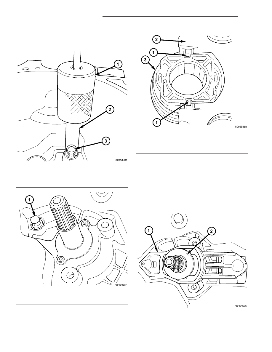
(32) If previously removed, install clutch release

lever pivot ball(s) using slide hammer C-3752 and
remover/installer 6891 (Fig. 74) (Fig. 75).

(33) Install clutch release bearing to lever. Apply

grease to interface (contact) points. Make sure
release bearing retainers engage lever pocket as
shown in (Fig. 76).

(34) Apply grease to pivot ball(s), and on release

lever at slave cylinder contact point.

(35) Install clutch release bearing/lever assembly

into position by sliding bearing onto input bearing
retainer, and using moderate hand pressure to seat
release lever to pivot ball (Fig. 77). A “pop” sound
should be heard. Verify proper engagement by lightly
pulling outward on lever at pivot ball location, and
then actuating lever and bearing to ensure proper
operation.

Fig. 74 Pivot Ball Removal/Installation

1 - C-3752 SLIDE HAMMER
2 - REMOVER/INSTALLER 6891
3 - PIVOT BALL

Fig. 75 Pivot Ball Position

1 - PIVOT BALL (1)

Fig. 76 Release Bearing-to-Lever

1 - RETAINER (2)
2 - RELEASE LEVER
3 - RELEASE BEARING

Fig. 77 Release Bearing and Lever

1 - RELEASE LEVER
2 - RELEASE BEARING

21 - 50

T850 MANUAL TRANSAXLE

RS

T850 MANUAL TRANSAXLE (Continued)

INSTALLATION

INSTALLATION - 2.4L GAS

(1) Install modular clutch assembly to transaxle.

Assemble transaxle to engine.

(2) Install and torque transaxle-to-engine bolts to

95 N·m (70 ft. lbs.).

(3) Raise transaxle/engine assembly into position

and

install

upper

mount

through-bolt.

Torque

through-bolt to 75 N·m (55 ft. lbs.).

(4) Remove screw jack.
(5) Install and torque modular clutch assembly-to-

drive plate bolts to 88 N·m (65 ft. lbs.)

(6) Install structural collar.
(7) Connect back-up lamp switch connector.
(8) Install starter motor into position (Fig. 78).

Install and torque bolts to 54 N·m (40 ft. lbs.).

(9) Install engine front mount bracket. Install and

torque bracket-to-transaxle bolts to 102 N·m (75 ft.
lbs.). Install and torque bracket-to-engine bolts to 68
N·m (50 ft. lbs.). Torque through-bolt and nut to 68
N·m (50 ft. lbs.).

(10) Install clutch slave cylinder into position, not-

ing orientation of different sized lugs (Fig. 79). While
depressing inward, rotate slave cylinder clockwise
60

t° into position until nylon locating tab rests

within transaxle case cutout, and hydraulic tube is
vertical. Connect “quick-connect” connection until an
audible “click” is heard. Verify connection by pulling
outward on connection.

(11) Install halfshafts and front wheel/tire assem-

blies. (Refer to 3 - DIFFERENTIAL & DRIVELINE/
HALF SHAFT - INSTALLATION)

(12) Lower vehicle.

Fig. 78 Starter Motor Removal/Installation

1 - STARTER MOTOR
2 - BOLT (3)

Fig. 79 Slave Cylinder Removal/Installation

1 - MOUNTING HOLE
2 - SLAVE CYLINDER
3 - ACCESS HOLE
4 - NYLON ANTI-ROTATION TAB
5 - QUICK CONNECT

RS

T850 MANUAL TRANSAXLE

21 - 51

T850 MANUAL TRANSAXLE (Continued)

(13) Install right mount bracket to transaxle (Fig.

80).

(14) Connect gearshift cables to shift levers/cover

assembly (Fig. 81). Install cables into position at
mount bracket and secure with retaining clips.

(15) Connect battery cables.
(16) Check transaxle fluid and engine coolant lev-

els. Adjust if necessary. (Refer to 21 - TRANSMIS-
SION/TRANSAXLE/MANUAL/FLUID - STANDARD
PROCEDURE)

INSTALLATION - 2.5L TD

(1) Assemble transaxle to engine, while aligning

transaxle input shaft to clutch disc splines.

(2) Install and torque transaxle-to-engine bolts to

95 N·m (70 ft. lbs.) (Fig. 82).

(3) Install transaxle upper mount (Fig. 83). Install

and torque four (4) mount-to-transaxle bolts to 54
N·m (40 ft. lbs.).

(4) Raise transaxle/engine assembly into position

and

install

upper

mount

through-bolt.

Torque

through-bolt to 75 N·m (55 ft. lbs.).

(5) Remove screw jack.
(6) Connect back-up lamp switch connector.
(7) Install starter motor into position (Fig. 84).

Install and torque bolts to 54 N·m (40 ft. lbs.).

Fig. 80 Transaxle Right Mount and Bracket

1 - MOUNT BRACKET
2 - BOLT (3)
3 - MOUNT
4 - BOLT (1)

Fig. 81 Gearshift Cables at Transaxle

1 - SELECTOR CABLE
2 - CABLE RETAINER
3 - CABLE RETAINER
4 - CROSSOVER CABLE
5 - MOUNT BRACKET

21 - 52

T850 MANUAL TRANSAXLE

RS

T850 MANUAL TRANSAXLE (Continued)

Fig. 82 Transaxle Removal/Installation

1 - TRANSAXLE
2 - BOLT

Fig. 83 Transaxle Upper Mount

1 - MOUNT
2 - BOLT (4)

Fig. 84 Starter Motor Removal/Installation

1 - STARTER MOTOR
2 - BOLT (3)

RS

T850 MANUAL TRANSAXLE

21 - 53

T850 MANUAL TRANSAXLE (Continued)


Content   ..  373  374  375  376   ..