Chrysler Town, Dodge Caravan. Manual - part 146
STANDARD PROCEDURE - TESTING FOR A
SHORT TO GROUND ON FUSES POWERING
SEVERAL LOADS
(1) Refer to the wiring diagrams and disconnect or
isolate all items on the suspected fused circuits.
(2) Replace the blown fuse.
(3) Supply power to the fuse by turning ON the
ignition switch or re-connecting the battery.
(4) Start connecting or energizing the items in the
fuse circuit one at a time. When the fuse blows the
circuit with the short to ground has been isolated.
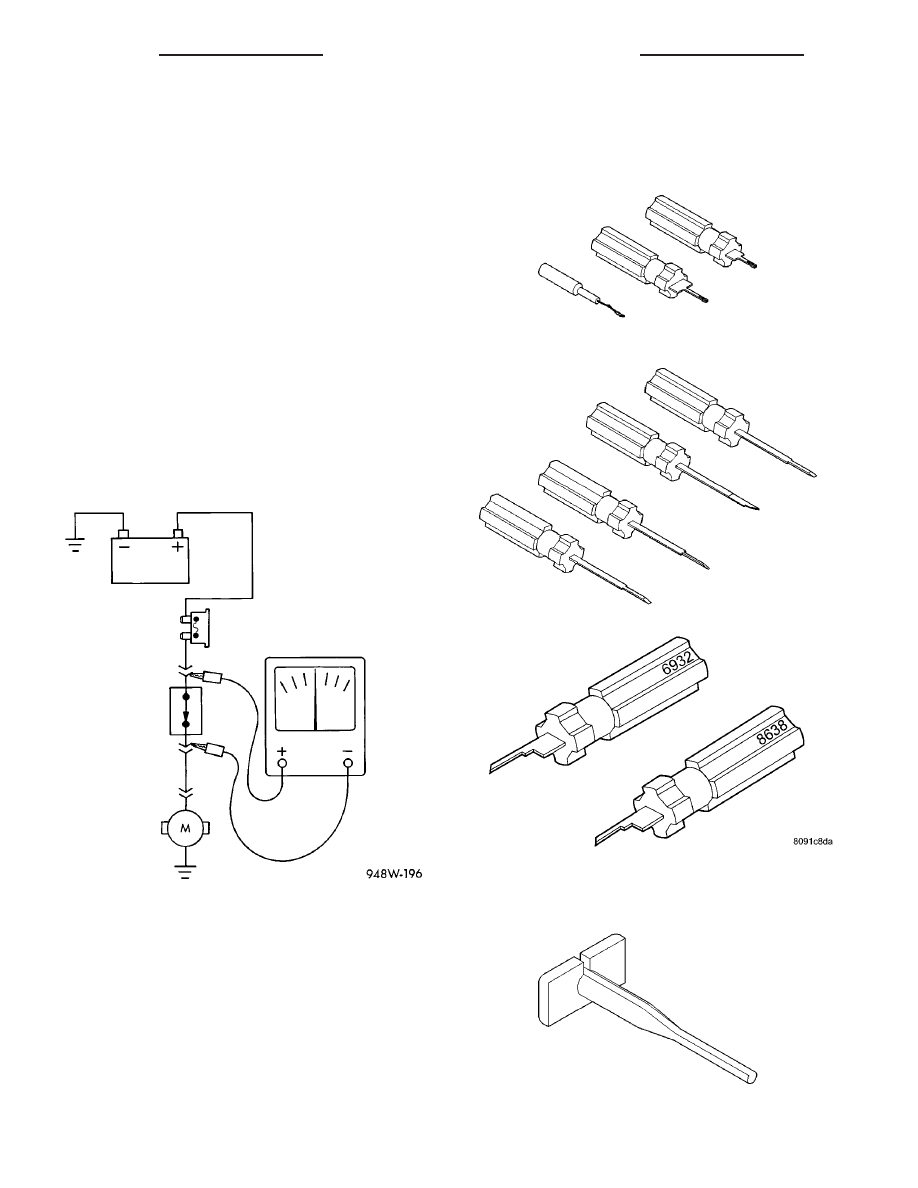
STANDARD PROCEDURE - TESTING FOR A
VOLTAGE DROP
(1) Connect the positive lead of the voltmeter to
the side of the circuit closest to the battery (Fig. 9).
(2) Connect the other lead of the voltmeter to the
other side of the switch, component or circuit.
(3) Operate the item.
(4) The voltmeter will show the difference in volt-
age between the two points.
SPECIAL TOOLS
WIRING/TERMINAL
Fig. 9 TESTING FOR VOLTAGE DROP
PROBING TOOL PACKAGE 6807
TERMINAL PICK TOOL SET 6680
TERMINAL REMOVING TOOLS 6932 AND 8638
TERMINAL REMOVING TOOL 6934
8W - 01 - 10
8W-01 WIRING DIAGRAM INFORMATION
RS
WIRING DIAGRAM INFORMATION (Continued)