Chrysler Town, Dodge Caravan. Manual - part 126


  Index      Chrysler     Chrysler TOWN & COUNTRY, VOYAGER, Dodge Caravan - service repair manual 2001-2007 year


Search            


Content   ..  124  125  126  127   ..


Chrysler Town, Dodge Caravan. Manual - part 126


DIAGNOSIS AND TESTING - POWER MIRRORS

(1) Remove Power Mirror Switch. (Refer to 8 -

ELECTRICAL/POWER MIRRORS/POWER MIRROR
SWITCH - REMOVAL).

(2) Disconnect wiring harness connector to the

power mirror switch and headlamp switch.

(3) Using two jumper wires:
• Connect one to a 12-volt source

• Connect the other to a good body ground

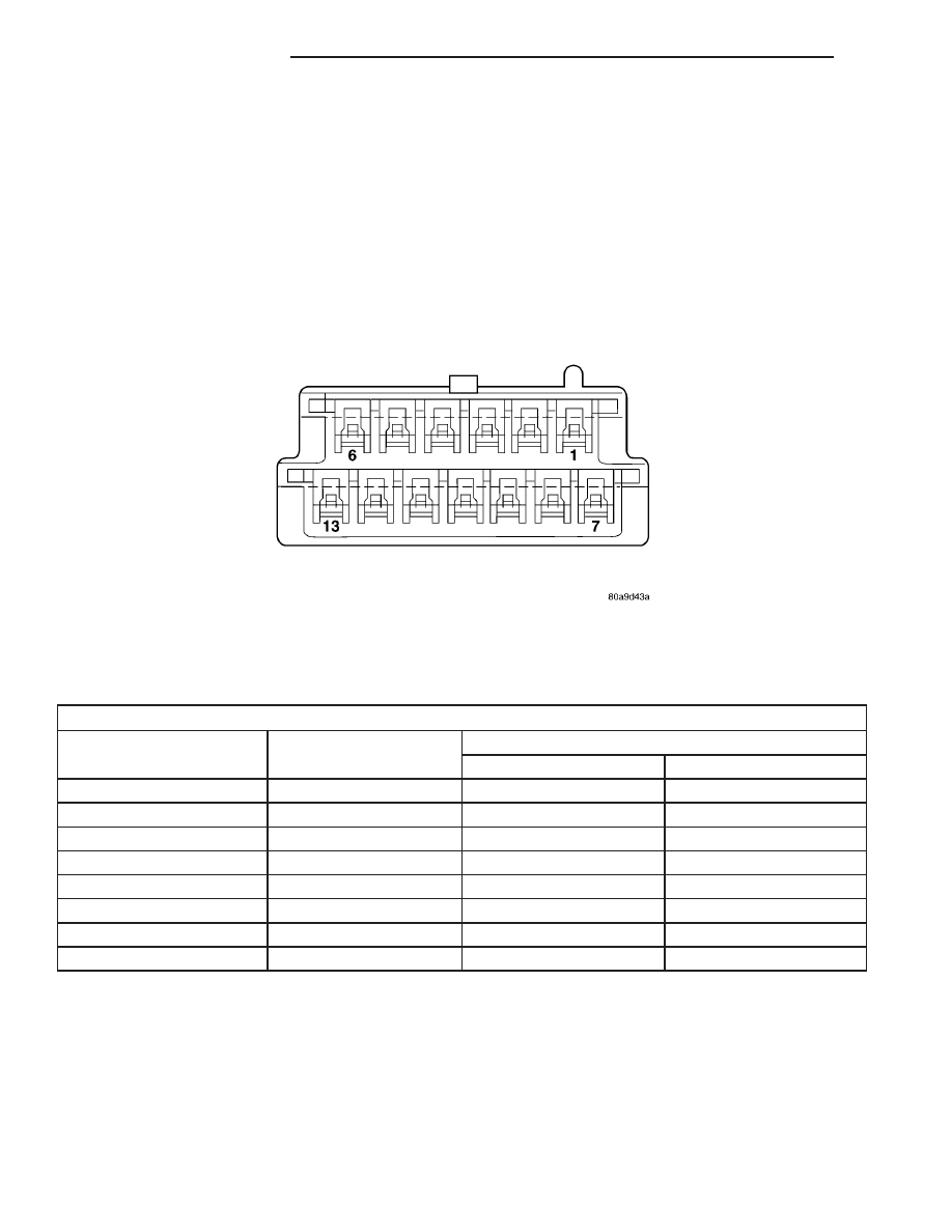
• Refer to the Mirror Test Chart for wire hookups

at the switch connector (Fig. 1).

POWER MIRROR MOTOR TEST

SWITCH CONNECTOR

12 Volts

Ground

MIRROR REACTION

Right

Left

PIN 12

PIN 6

UP

PIN 7

PIN 6

LEFT

PIN 6

PIN 12

DOWN

PIN 6

PIN 7

RIGHT

PIN 13

PIN 1

UP

PIN 8

PIN 1

LEFT

PIN 1

PIN 13

DOWN

PIN 1

PIN 8

RIGHT

(4) If results shown in table are not obtained,

check for broken or shorted circuit, or replace mirror
assembly as necessary.

Fig. 1 Power Mirror Connector

8N - 46

POWER MIRRORS

RS

POWER MIRRORS (Continued)

AUTOMATIC DAY / NIGHT
MIRROR

DESCRIPTION

An automatic dimming inside day/night rear view

mirror and an automatic dimming driver side outside
rear

view

mirror

are

available

factory-installed

options on this model. Following is a general descrip-
tion of this optional equipment.

The automatic day/night mirror is able to automat-

ically change its reflectance. A thin layer of electro-
chromic material between two pieces of conductive
glass make up the face of the mirror. Two photocell
sensors are used to monitor light levels and adjust
the reflectance of the mirror to reduce the glare of
headlamps approaching the vehicle from the rear.

For removal procedures, (Refer to 23 - BODY/IN-

TERIOR/REAR VIEW MIRROR - REMOVAL).

OPERATION

The ambient photocell sensor faces forward, to

detect the outside light levels. A second sensor faces
rearward to detect the light level received through
the vehicles back window. When the difference
between the two light levels becomes too great (the
light level received at the rear of the mirror is much
higher than that at the front of the mirror), the mir-
ror begins to darken.

The mirror switch allows the driver a manual con-

trol of whether the automatic dimming feature is
operational. When AUTO is selected a small Light-
Emitting Diode (LED), to the right of the mirror
switch, is illuminated. The automatic dimming fea-
ture will only operate when the ignition switch is in
the On position. The mirror also senses the backup
lamp circuit, and will automatically disable its self-
dimming feature whenever the transmission gear
selector is in the Reverse position.

NOTE: The mirror always defaults to an ON state
upon ignition.

The driver side automatic dimming mirror is stan-

dard with the automatic dimming inside mirror. The
signal to control the dimming of that mirror is gen-
erated by the automatic day/night inside rear view
mirror circuitry. That signal is then delivered to the
driver side outside rear view mirror on a hard wired
circuit.

The

automatic

day/night

mirror

cannot

be

repaired. If faulty or damaged, the entire inside rear
view mirror assembly must be replaced.

DIAGNOSIS AND TESTING - AUTOMATIC DAY /
NIGHT MIRROR

For circuit descriptions and diagrams, refer to the

appropriate wiring information. The wiring informa-
tion includes wiring diagrams, proper wire and con-
nector repair procedures, details of wire harness
routing and retention, connector pin-out information
and location views for the various wire harness con-
nectors, splices and grounds.

(1) Check the fuse in the intelligent power module.

If OK, go to Step 2. If not OK, repair the shorted cir-
cuit or component as required and replace the faulty
fuse.

(2) Turn the ignition switch to the On position.

Check for battery voltage at the fuse in the intelli-
gent power module. If OK, go to Step 3. If not OK,
repair the open circuit to the ignition switch as
required.

(3) Unplug the wire harness connector from the

automatic day/night mirror. Check for battery voltage
at the fused ignition switch output circuit cavity of
the automatic day/night mirror wire harness connec-
tor. If OK, go to Step 4. If not OK, repair the open
circuit to the junction block as required.

(4) Turn the ignition switch to the Off position.

Check for continuity between the ground circuit cav-
ity of the automatic day/night mirror wire harness
connector and a good ground. There should be conti-
nuity. If OK, go to Step 5. If not OK, repair the cir-
cuit to ground as required.

(5) Turn the ignition switch to the On position. Set

the parking brake. Place the transmission gear selec-
tor lever in the Reverse position. Check for battery
voltage at the backup lamp switch output circuit cav-
ity of the automatic day/night mirror wire harness
connector. If voltage is present, reinstall the auto-
matic day/night mirror wire harness connector and
go to Step 6. If not OK, repair the open circuit as
required.

(6) Place the transmission gear selector lever in

the Neutral position. Place the automatic day/night
mirror switch in the On (LED in the switch is
lighted) position. Cover the forward facing ambient
photocell sensor to keep out any ambient light.

NOTE: The ambient photocell sensor must be cov-
ered completely, so that no light reaches the sen-
sor. Use a finger pressed tightly against the sensor,
or cover the sensor completely with electrical tape.

(7) Shine a light into the rearward facing headlamp

photocell sensor. The automatic day/night mirror
should darken. The automatic day/night mirror should
darken within 2 minutes if testing for the first time.
For immediate response, turn the vehicle OFF and
back ON with the forward-facing light sensor still cov-

RS

POWER MIRRORS

8N - 47

ered. This defeats the day-detect logic. If OK, go to
Step 8. If not OK, replace the faulty mirror unit.

(8) With the mirror darkened, place the transmis-

sion gear selector lever in the Reverse position. The
automatic day/night mirror should return to its nor-
mal reflectance. If not OK, replace the faulty mirror
unit.

Bench testing both mirrors can be done, of care is

exercised. For an inside mirror, the pin closest to he
mount is 12V (+), the next is 12V (-). The third is
reverse override. The fourth is outside mirror (+),
and the fifth is outside mirror (-). Do not apply 12
volts to the fourth and fifth pins. 
With 12 volts
on pins 1 and 2, the mirror can be tested by blocking
the rear sensor and shining a light into the forward
sensor. For an outside mirror, there is a 2–pin con-
nector. Applying 1.2 volts will cause the mirror to
dim. If the mirror does not dim, the entire glass
assembly can be replaced just as it is when the glass
is broken.

WARNING: Do not apply 12 volts to the outside mir-
ror. Damage to the mirror will result.

POWER FOLDAWAY MIRROR
SWITCH - EXPORT

DESCRIPTION

These vehicles may be equipped with Power Fold-

away Mirrors. This feature allows both the driver
and passenger side view mirrors to fold inward
(retract) on demand. The vehicle has an additional
switch located on the steering column that controls
the folding function of the mirror assembly (Fig. 2).

The fold-away side view mirror is attached to the

vehicle’s door in the same manner as mirrors without
the fold-away option. The fold-away mirrors unique
option is the internal motor which allows the mirrors
to fold inward on demand. The fold-away mirror
motor is not serviceable separately and if a motor is
found to be faulty the entire side view mirror must
be replaced.

OPERATION

When the mirror retract switch is depressed, both

of the side view mirrors will fold inward, Thus mak-
ing the overall width of the vehicle the smallest pos-
sible. This can be helpful were parking space is a
absolute minimum.

When the driver’s door is opened, only the driver’s

door mirror will unfold. If the passenger door is
opened, both mirrors will unfold.

The power fold away mirror system consists of the

following components: mirror switch, side view mir-

ror, relay, wires and fuse. Refer to the appropriate
wiring information. The wiring information includes
wiring diagrams, proper wire and connector repair
procedures, details of wire harness routing and
retention, connector pin-out information and location
views for the various wire harness connectors, splices
and grounds.

REMOVAL

(1) Disconnect and isolate the battery negative

cable.

(2) Remove the upper and lower steering column

shroud (Refer to 19 - STEERING/COLUMN/LOWER
SHROUD - REMOVAL).

(3) Disconnect electrical harness connector.

(4) Remove switch from steering column shroud

(Fig. 3).

Fig. 2 POWER FOLDAWAY MIRROR SWITCH

1 - POWER FOLDAWAY MIRROR SWITCH
2 - STEERING COLUMN

Fig. 3 POWER FOLDING MIRROR SWITCH

1 - STEERING COLUMN SHROUD
2 - POWER FOLDAWAY SWITCH

8N - 48

POWER MIRRORS

RS

AUTOMATIC DAY / NIGHT MIRROR (Continued)

INSTALLATION

(1) Install switch to steering column shroud.
(2) Connect wire harness connector.
(3) Install the upper and lower steering column

shroud (Refer to 19 - STEERING/COLUMN/LOWER
SHROUD - INSTALLATION).

(4) Connect the battery negative cable.

REMOTE SWITCH

DIAGNOSIS AND TESTING - REMOTE SWITCH

(1) Remove power mirror switch. (Refer to 8 -

ELECTRICAL/POWER MIRRORS/POWER MIRROR
SWITCH - REMOVAL).

(2) Disconnect wiring harness at switch connector.
(3) Using a ohmmeter, test for continuity between

the terminals of the switch (Fig. 4).

MIRROR SWITCH TEST

MIRROR SELECT SWITCH IN “LEFT”
POSITION

Move

Button

Continuity Between

UP

PIN 9 - PIN 12,

PIN 6 - PIN 11,

PIN 9 - PIN 13

LEFT

PIN 9 - PIN 7,

PIN 6 - PIN 11,

PIN 9 - PIN 8

DOWN

PIN 9 - PIN 6,

PIN 12 - PIN 11,

PIN 13 - PIN 11

RIGHT

PIN 9 - PIN 6,

PIN 7 - PIN 11,

PIN 8 - PIN 11

MIRROR SELECT SWITCH IN “RIGHT”
POSITION

Move

Button

Continuity Between

UP

PIN 9 - PIN 13,

PIN 1 - PIN 11,

PIN 9 - PIN 12

MIRROR SELECT SWITCH IN “LEFT”
POSITION

LEFT

PIN 9 - PIN 8,

PIN 1 - PIN 11,

PIN 9 - PIN 7

DOWN

PIN 9 - PIN 1,

PIN 13 - PIN 11,

PIN 12 - PIN 11

RIGHT

PIN 9 - PIN 1,

PIN 8 - PIN 11,

PIN 7 - PIN 11

(4) If results shown in the table are not obtained,

replace the switch.

REMOVAL

(1) Disconnect and isolate the battery negative

cable.

(2) Remove instrument panel lower cover.
(3) From

behind

headlamp

switch

assembly,

depress retaining tabs and push switch from instru-
ment panel.

(4) Disconnect wire connector from power mirror

switch.

(5) Disengage lock tabs above and below the mir-

ror switch.

(6) Remove power mirror switch from headlamp

switch bezel.

INSTALLATION

(1) Install power mirror switch to the headlamp

switch bezel.

(2) Connect wire connector to the power mirror

switch.

(3) Insert headlamp switch assembly into instru-

ment panel.

(4) Install instrument panel lower cover.
(5) Connect battery negative cable.

SIDEVIEW MIRROR

REMOVAL

For service procedures, (Refer to 23 - BODY/EXTE-

RIOR/SIDE VIEW MIRROR - REMOVAL).

Fig. 4 Mirror Switch

RS

POWER MIRRORS

8N - 49

POWER FOLDAWAY MIRROR SWITCH - EXPORT (Continued)


Content   ..  124  125  126  127   ..