Chrysler Town, Dodge Caravan. Manual - part 71


  Index      Chrysler     Chrysler TOWN & COUNTRY, VOYAGER, Dodge Caravan - service repair manual 2001-2007 year


Search            


Content   ..  69  70  71  72   ..


Chrysler Town, Dodge Caravan. Manual - part 71


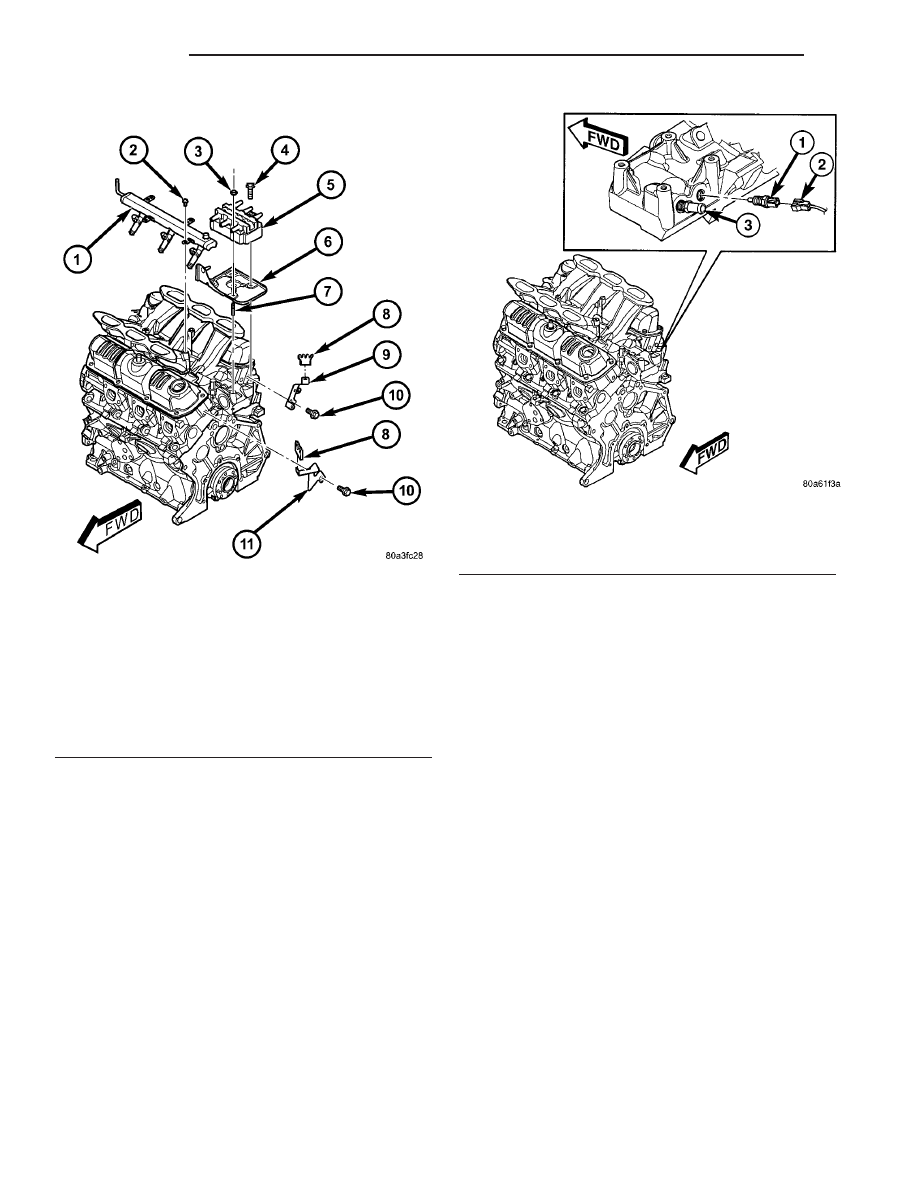
(3) Remove ignition coil and bracket (Fig. 5).

(4) Disconnect coolant sensor electrical connector

(Fig. 6).

(5) Remove coolant sensor (Fig. 6).

INSTALLATION

(1) Install engine coolant temperature sensor (Fig.

6). Tighten sensor to 7 N·m (60 in. lbs.).

(2) Connect electrical connector to sensor (Fig. 6).
(3) Install ignition coil bracket (Fig. 5).
(4) Install ignition coil (Fig. 5).
(5) Install power steering reservoir (Fig. 4).
(6) Fill cooling system. (Refer to 7 - COOLING -

STANDARD PROCEDURE)

ENGINE COOLANT
THERMOSTAT

DESCRIPTION

The engine cooling thermostats are a wax pellet

driven, reverse poppet choke type. The thermostat is
mounted in a housing on the coolant outlet of the
engine (Fig. 8) or (Fig. 10).

OPERATION

The engine cooling thermostat is a wax pellet

driven, reverse poppet choke type. The thermostat is
designed to provide the fastest warm up possible by
preventing leakage through it and to guarantee a
minimum engine operating temperature of 88 to
93°C (192 to 199°F). The thermostat also will auto-
matically reach wide open so it will not restrict flow
to the radiator as temperature of the coolant rises in
hot weather to around 104°C (220°F). Above this
temperature the coolant temperature is controlled by
the radiator, fan, and ambient temperature, not the
thermostat.

The thermostat is operated by a wax filled con-

tainer (pellet) which is sealed. When heated coolant
reaches

a

predetermined

temperature,

the

wax

expands enough to overcome the closing spring and
water pump pressure, which forces the valve to open.

Fig. 5 Fuel Rail, Ignition Coil and Bracket

1 - FUEL RAIL
2 - BOLT - FUEL RAIL
3 - NUT - IGNITION COIL
4 - BOLT - IGNITION COIL
5 - IGNITION COIL
6 - BRACKET - IGNITION COIL
7 - STUD - IGNITION COIL
8 - SEPARATOR - SPARK PLUG CABLE
9 - BRACKET - SPARK PLUG CABLE SEPARATOR
10 - BOLT - SEPARATOR BRACKET
11 - BRACKET - SPARK PLUG CABLE SEPARATOR

Fig. 6 Engine Coolant Temperature Sensor

1 - ENGINE COOLANT TEMPERATURE SENSOR
2 - CONNECTOR - ENGINE COOLANT SENSOR
3 - FITTING - HEATER SUPPLY

7 - 22

ENGINE

RS

ENGINE COOLANT TEMPERATURE SENSOR - 3.3/3.8L (Continued)

DIAGNOSIS AND TESTING - ENGINE COOLANT
THERMOSTAT

The thermostat is operated by a wax filled cham-

ber (pellet) which is sealed. When heated coolant
reaches a predetermined temperature the wax pellet
expands enough to overcome the closing spring and
water pump pressure, which forces the valve to open.
Coolant leakage into the pellet will cause a thermo-
stat to fail open. Do not attempt to free up a thermo-
stat with a screwdriver.

Thermostat diagnostics is included in powertrain

control module’s (PCM) programing for on-board
diagnosis. The malfunction indicator light (MIL) will
illuminate and a diagnostic trouble code (DTC) will
be set when an “open too soon” condition occurs. Do
not change a thermostat for lack of heater perfor-
mance or temperature gauge position, unless a DTC
is present. For other probable causes, (Refer to 7 -
COOLING/ENGINE - DIAGNOSIS AND TESTING).
Thermostat failing shut is the normal long term
mode of failure, and normally, only on high mileage
vehicles. The temperature gauge will indicate this
(Refer to 7 - COOLING/ENGINE - DIAGNOSIS AND
TESTING).

ENGINE COOLANT
THERMOSTAT - 2.4L

REMOVAL

(1) Drain cooling system below the thermostat

level. (Refer to 7 - COOLING - STANDARD PROCE-
DURE)

(2) Remove radiator upper hose from the coolant

outlet housing (Fig. 7).

(3) Remove coolant outlet housing bolts and hous-

ing (Fig. 8).

(4) Remove thermostat. Discard gasket and clean

both gasket sealing surfaces.

INSTALLATION

(1) Place a new gasket (dipped in clean water) on

the coolant outlet connector surface. Position thermo-
stat with air bleed at the 12 o’clock position in ther-
mostat housing (Fig. 8).

(2) Position the coolant outlet connector and gas-

ket over the thermostat, making sure thermostat is
seated in the thermostat housing.

(3) Position outlet connector to thermostat housing

and install bolts (Fig. 8). Tighten bolts to 28 N·m
(250 in. lbs.).

(4) Install the radiator upper hose to coolant outlet

housing (Fig. 7).

(5) Refill the cooling system. (Refer to 7 - COOL-

ING - STANDARD PROCEDURE)

ENGINE COOLANT
THERMOSTAT - 3.3/3.8L

REMOVAL

(1) Drain cooling system down below the thermo-

stat level. (Refer to 7 - COOLING - STANDARD
PROCEDURE)

(2) Remove radiator upper hose from coolant outlet

connector (Fig. 9).

Fig. 7 RADIATOR HOSES TO ENGINE - 2.4L

1 - UPPER HOSE
2 - LOWER HOSE

Fig. 8 Thermostat and Outlet Connector - 2.4L

Engine

1 - THERMOSTAT
2 - GASKET
3 - COOLANT OUTLET CONNECTOR
4 - BOLT

RS

ENGINE

7 - 23

ENGINE COOLANT THERMOSTAT (Continued)

(3) Remove coolant outlet connector bolts and con-

nector (Fig. 10).

(4) Remove thermostat from outlet connector.
(5) Discard gasket and clean both gasket sealing

surfaces.

INSTALLATION

(1) To ensure proper seating of replacement ther-

mostat, carefully remove the bulged metal from the

wall of the outlet connector recess that was created
during the staking procedure that held the OEM
thermostat in place (Fig. 11). It is not necessary to
restake the replacement thermostat into the connec-
tor.

(2) Position thermostat to coolant outlet connector.

Align the two locating notches on thermostat to the
connector (Fig. 12). This position will ensure proper
location of the thermostat air bleed.

Fig. 9 RADIATOR HOSES TO ENGINE - 3.3/3.8L

1 - UPPER HOSE
2 - LOWER HOSE

Fig. 10 THERMOSTAT - 3.3/3.8L ENGINE

1 - COOLANT OUTLET CONNECTOR
2 - BOLT
3 - THERMOSTAT
4 - GASKET

Fig. 11 Connector Staking Material Removal

1 - STAKE
2 - OUTLET CONNECTOR

Fig. 12 Thermostat Position In Outlet Connector

1 - LOCATING NOTCH
2 - THERMOSTAT
3 - COOLANT OUTLET CONNECTOR

7 - 24

ENGINE

RS

ENGINE COOLANT THERMOSTAT - 3.3/3.8L (Continued)

(3) Position a new gasket over the thermostat and

connector making sure thermostat is in proper posi-
tion and in the recess provided.

(4) Install thermostat and connector assembly to

the intake manifold (Fig. 10). Tighten bolts to 28
N·m (250 in. lbs.).

(5) Install the radiator upper hose to coolant outlet

connector (Fig. 9).

(6) Refill the cooling system to the proper level.

(Refer to 7 - COOLING - STANDARD PROCEDURE)

RADIATOR

REMOVAL

(1) Disconnect negative cable from battery.
(2) Remove radiator upper crossmember support.

(Refer to 23 - BODY/EXTERIOR/GRILLE OPENING
REINFORCEMENT - REMOVAL)

WARNING:

DO

NOT

REMOVE

THE

CYLINDER

BLOCK PLUG OR THE RADIATOR DRAINCOCK
WITH THE SYSTEM HOT AND UNDER PRESSURE
BECAUSE SERIOUS BURNS FROM COOLANT CAN
OCCUR.

(3) Drain the cooling system. (Refer to 7 - COOL-

ING - STANDARD PROCEDURE)

(4) Remove the radiator fans. (Refer to 7 - COOL-

ING/ENGINE/RADIATOR FAN - REMOVAL)

(5) Disconnect coolant reserve/recovery hose.
(6) Remove vapor purge solenoid from mounting

bracket.

(7) Disconnect upper and lower hoses from the

radiator (Fig. 13) or (Fig. 14).

(8) Remove the A/C condenser side brackets to

radiator attaching screws (Fig. 15). Separate the con-
denser from the radiator by lifting upward to disen-
gage

from

lower

mounts

(Fig.

15).

Allow

the

condenser to rest in front of radiator.

(9) Radiator can now be lifted free from engine

compartment. Care should be taken not to dam-
age radiator cooling fins or water tubes during
removal.

INSTALLATION

(1)

Be sure the air seal is in position before

radiator is installed. Slide radiator down into posi-
tion. Seat the radiator with the rubber isolators into
the mounting holes provided, with a 10 lbs. force.

(2) Position air conditioning condenser onto the

radiator lower mounts and install upper screws (Fig.
15). Tighten fasteners to 5 N·m (45 in. lbs.).

(3) Install the radiator upper and lower hoses (Fig.

13) or (Fig. 14).

(4) Connect the coolant reserve/recovery hose.
(5) Connect the vapor purge solenoid to the mount-

ing bracket.

(6) Install the radiator fans. (Refer to 7 - COOL-

ING/ENGINE/RADIATOR FAN - INSTALLATION)

(7) Install the radiator upper crossmember sup-

port.

(Refer

to

23

-

BODY/EXTERIOR/GRILLE

OPENING REINFORCEMENT - INSTALLATION)

(8) Fill the cooling system. (Refer to 7 - COOLING

- STANDARD PROCEDURE)

(9) Connect negative cable to battery.

Fig. 13 Radiator Hoses to Radiator - 2.4L

1 - UPPER HOSE
2 - LOWER HOSE
3 - HOSE SUPPORT CLIP

Fig. 14 Radiator Hoses to Radiator - 3.3/3.8L

1 - UPPER HOSE
2 - LOWER HOSE

RS

ENGINE

7 - 25

ENGINE COOLANT THERMOSTAT - 3.3/3.8L (Continued)


Content   ..  69  70  71  72   ..