Chrysler PT Cruiser. Manual - part 984


  Index      Chrysler     Chrysler PT Cruiser - service repair manual 2005 year


Search            


Content   ..  982  983  984  985   ..


Chrysler PT Cruiser. Manual - part 984


(8) Disconnect the A/C suction line from the accu-

mulator tube tapping block and remove and discard
the O-ring seal.

(9) Install plugs in, or tape over the opened suc-

tion line fitting and the accumulator tube tapping
block outlet port.

(10) Remove the A/C suction line from the engine

compartment.

INSTALLATION

NOTE: Replacement of the refrigerant line O-ring
seals is required anytime a refrigerant line is
opened. Failure to replace the rubber O-ring seals
could result in a refrigerant system leak.

(1) Position the A/C suction line into the engine

compartment.

(2) Remove the tape or plugs from the suction line

fitting and the accumulator tube tapping block.

(3) Lubricate a new rubber O-ring seal with clean

refrigerant oil and install it on the suction line fit-
ting. Use only the specified O-ring as it is made of a
special material for the R-134a system. Use only
refrigerant oil of the type recommended for the A/C
compressor in the vehicle.

(4) Connect the A/C suction line to the accumula-

tor tube tapping block.

(5) Install the nut that secures the A/C suction

line to the accumulator tube tapping block. Tighten
the nut to 5 N·m (44 in. lbs.).

(6) If equipped with the 2.4L Turbo engine, install

the nut that secures the suction line retaining
bracket to the thermostat housing stud bolt. Tighten
the nut to 2 N·m (17 in. lbs.).

(7) Remove the tape or plugs from the suction line

fitting and the compressor port.

(8) Lubricate a new rubber O-ring seal with clean

refrigerant oil and install it on the suction line fit-
ting. Use only the specified O-ring as it is made of a
special material for the R-134a system. Use only
refrigerant oil of the type recommended for the A/C
compressor in the vehicle.

(9) Connect the A/C suction line to the A/C com-

pressor.

(10) Install the bolt that secures the A/C suction

line to the A/C compressor. Tighten the bolt to 12
N·m (106 in. lbs.).

(11) Reconnect the negative battery cable.
(12) Evacuate the refrigerant system (Refer to 24 -

HEATING & AIR CONDITIONING - STANDARD
PROCEDURE - REFRIGERANT SYSTEM EVACU-
ATE).

(13) Recharge the refrigerant system (Refer to 24 -

HEATING & AIR CONDITIONING - STANDARD
PROCEDURE

-

REFRIGERANT

SYSTEM

CHARGE).

SERVICE PORT VALVE CORE

DESCRIPTION

The A/C service port valve cores are serviceable

items (Fig. 24) and (Fig. 25). The low side valve is
located on the liquid line near the accumulator. The

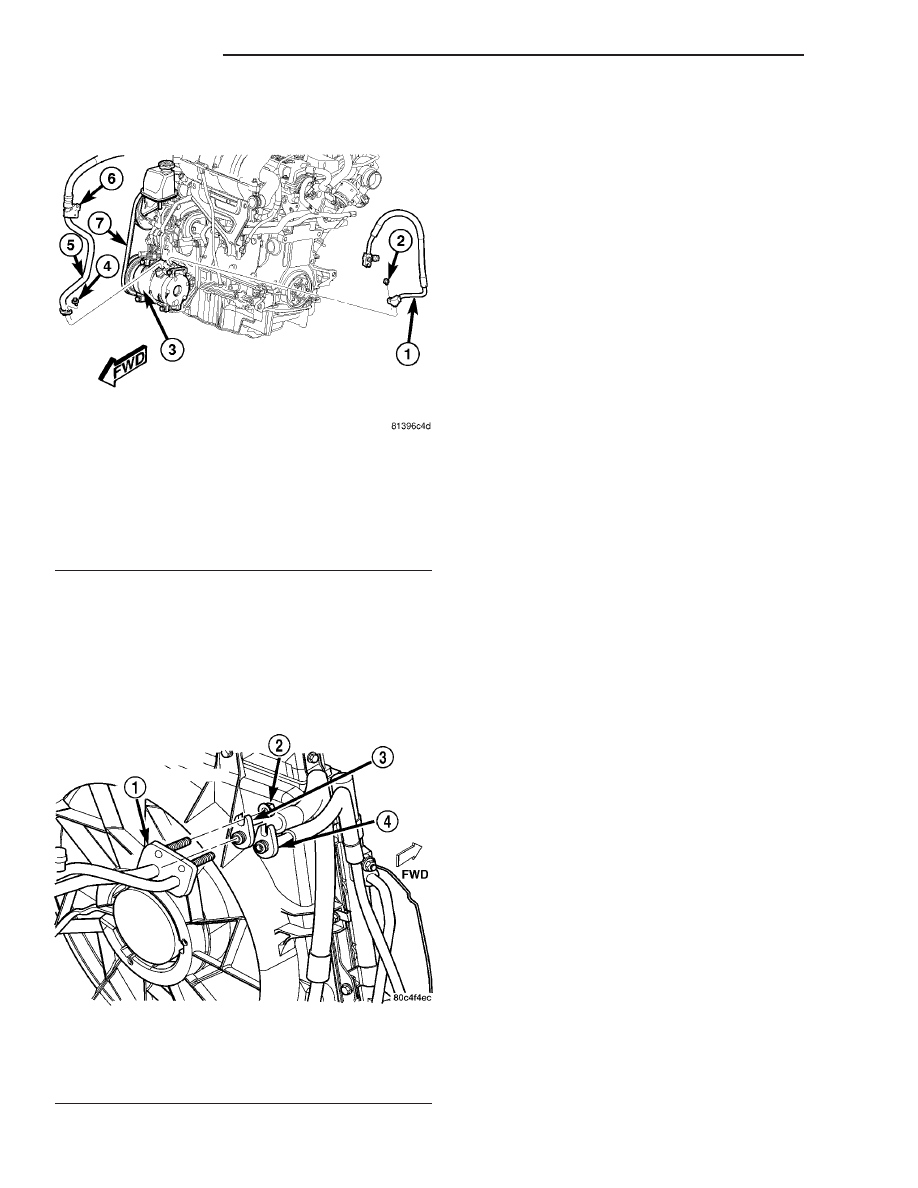
Fig. 22 A/C Compressor Refrigerant Lines - Typical

1 - A/C DISCHARGE LINE
2 - BOLT
3 - A/C COMPRESSOR
4 - BOLT
5 - A/C SUCTION LINE
6 - SUCTION LINE RETAINING BRACKET
7 - ACCESSORY DRIVE BELT

Fig. 23 A/C Refrigerant Lines - Typical

1 - ACCUMULATOR TUBE TAPPING BLOCK
2 - NUT (2)
3 - A/C SUCTION LINE
4 - A/C LIQUID LINE

24 - 58

PLUMBING

PT

SUCTION LINE (Continued)

high side valve is located on the discharge line near
the compressor.

REMOVAL

WARNING: Review safety precautions and warnings
in this group before performing this procedure
(Refer to 24 - HEATING & AIR CONDITIONING/
PLUMBING - WARNINGS) and (Refer to 24 - HEAT-
ING & AIR CONDITIONING/PLUMBING - CAUTIONS).
Failure to follow the warnings and cautions could
result in possible personal injury or death.

(1) Remove the protective cap from the low and/or

high side service port as necessary.

(2) Recover the refrigerant from the refrigerant

system (Refer to 24 - HEATING & AIR CONDITION-
ING/PLUMBING/REFRIGERANT

-

STANDARD

PROCEDURE - REFRIGERANT SYSTEM RECOV-
ERY).

(3) Using a standard Schrader-type valve core tool,

remove the valve core from the service port as
required.

(4) Install a plug in or tape over the opened ser-

vice port.

INSTALLATION

(1) Lubricate the A/C service port valve core with

clean refrigerant oil prior to installation. Use only
refrigerant oil of the type recommended for the A/C
compressor in the vehicle.

(2) Remove the tape or plug from the A/C service

port.

(3) Using a standard Schrader-type valve core tool,

install and tighten the replacement valve core into
the A/C service ports as required.

CAUTION: A valve core that is not fully seated in the
A/C service port can result in damage to the valve
during refrigerant system evacuation and charge.
Such damage may result in a loss of system refrig-
erant while uncoupling the charge adapters.

(4) Evacuate the refrigerant system (Refer to 24 -

HEATING & AIR CONDITIONING/PLUMBING -
FRONT/REFRIGERANT

-

STANDARD

PROCE-

DURE - REFRIGERANT SYSTEM EVACUATE).

(5) Charge the refrigerant system (Refer to 24 -

HEATING & AIR CONDITIONING/PLUMBING -
FRONT/REFRIGERANT

-

STANDARD

PROCE-

DURE - REFRIGERANT SYSTEM CHARGE).

(6) Install the protective cap onto the A/C service

ports as required.

Fig. 24 Low Side Service Port - Typical

1 - LOW SIDE SERVICE PORT
2 - WIRE HARNESS CONNECTOR
3 - EVAPORATOR TUBE TAPPING BLOCK
4 - BOLT
5 - ACCUMULATOR
6 - A/C LOW PRESSURE SWITCH

Fig. 25 High Side Service Port - Typical

1 - LIQUID LINE
2 - SUCTION LINE
3 - A/C COMPRESSOR
4 - DISCHARGE LINE
5 - HIGH SIDE SERVICE PORT

PT

PLUMBING

24 - 59

SERVICE PORT VALVE CORE (Continued)

DIESEL ENGINE COOLANT HEATER

TABLE OF CONTENTS

page

page

DIESEL ENGINE COOLANT HEATER

DESCRIPTION

. . . . . . . . . . . . . . . . . . . . . . . . . 60

OPERATION

. . . . . . . . . . . . . . . . . . . . . . . . . . . 60

DIAGNOSIS AND TESTING

DIESEL ENGINE COOLANT HEATER

. . . . . . 60

HEATER UNIT

REMOVAL

. . . . . . . . . . . . . . . . . . . . . . . . . . . . . 61

INSTALLATION

. . . . . . . . . . . . . . . . . . . . . . . . . 61

DIESEL ENGINE COOLANT
HEATER

DESCRIPTION

Vehicles equipped with the diesel engine are also

equipped with a engine coolant heater system. This
engine coolant heater is used to preheat the engine
coolant to aid in cabin heating. Engine coolant is pre-
heated using resistance heating. Current is supplied
to the three glow plug type heating elements which
reside in a single heater housing in the stream of
engine coolant. As the coolant is routed from the
engine, it passes over the ends of the glow plugs, the
heat is transferred to the coolant and then to the
heater core. This provides additional heat to the pas-
senger

compartment.

The

diesel

engine

coolant

heater system is interfaced to the vehicles on-board
computer system and DRBIII

t diagnostics.

OPERATION

With the ignition turned to the On position, three

temperature sensors record the ambient air in order
to determine if it is cold enough to turn on the diesel
engine coolant heater. One sensor is in the vehicle on
the battery, under the driver’s seat. The other two
sensors are in the engine compartment (inlet air tem-
perature and manifold temperature). Based in the
lowest temperature of the three temperature sensors,
a pre-determined coolant temperature set point is
established at which the diesel engine coolant heat-
ers will shut off.

For example, if the lowest recorded temperature

from the three sensors is 0° C (32° F) or below, the
heaters will shut off when the coolant temperature
reaches 75° C (167° F). If the lowest ambient air tem-
perature at key on is 10° C (50° F) or higher, then
the heaters will not turn on.

There are three heating elements in the assembly:

Plug 1 = 300 W, Plug 2 = 400 W and Plug 3 = 300 W.
Plug 1 is tied to one relay, while plugs 2 and 3 are
tied to a second relay. Because there are 3 plugs with
only 2 relays, when the auxiliary diesel engine cool-

ant heater is enabled by the engine controller, the fir-
ing sequence is as follows:

• a) Plug 1 only.

• b) Plugs 2 and 3 only.

• c) Plugs 1 to 3.
At each step, the powertrain control module (PCM)

monitors loads on the electrical system to see if it is
OK to proceed to the next phase of the firing
sequence. The system will back out in the reverse
order when a problem is encountered.

DIAGNOSIS AND TESTING

DIESEL ENGINE COOLANT HEATER

The DRB-III

t scan tool is programmed to allow the

technician to turn each diesel engine coolant heater
relay on and off at a predetermined number of sec-
onds. During this point, a voltage drop across each
relay can be measured in order to determine whether
they are functioning properly.

NOTE: This process should be performed anytime a
vehicle is serviced for a significant coolant loss.
Glow plug life is affected whenever the diesel
engine coolant heater is operated with NO or LOW
COOLANT FLOW across the glow plug tips.

Checking the glow plug heating element entails

measuring the resistance across each glow plug at
room temperature (appx. 23° C, 74° F). Unplug the
4–way heater wire connector from the headlamp/dash
wiring harness at the rear of the engine (rearward in
vehicle above the exhaust manifold). Using an ohm-
meter, measure the resistance across each glow plug
by touching one probe to the diesel engine coolant
heater housing (ground) and the other probe to one of
the terminals in the female heater connector corre-
sponding to each plug (pin 1= glow plug 1, pin
2=glow plug 2, etc.). Each heating element is func-
tioning

properly

if

the

measured

resistance

is

between 250–800 mOhm (0.25–0.8 Ohm) at room
temperature (23° C, 74° F).

24 - 60

DIESEL ENGINE COOLANT HEATER

PT

If one or more heating elements has a measured

resistance outside this range and is not functioning
properly then the entire diesel engine coolant heater
must be replaced.

HEATER UNIT

REMOVAL

WARNING: Review safety precautions and warnings
in this group before performing this procedure
(Refer to 24 - HEATING & AIR CONDITIONING/
PLUMBING - WARNINGS) and (Refer to 24 - HEAT-
ING & AIR CONDITIONING/PLUMBING - CAUTIONS).
Failure to follow the warnings and cautions could
result in possible personal injury or death.

(1) Disconnect and isolate the negative battery

cable.

(2) Drain the engine cooling system (Refer to 7 -

COOLING/ENGINE/COOLANT - STANDARD PRO-
CEDURE - DRAINING COOLING SYSTEM).

(3) Disconnect the wire harness connector for the

diesel engine coolant heater from the engine wire
harness connector and remove the heater connector
from the connector locating bracket (Fig. 1).

(4) Remove the hose clamp from each end of the

diesel engine coolant heater.

(5) Remove the hoses from each end of the diesel

engine coolant heater.

(6) Remove the bolt that secures the diesel engine

coolant heater bracket to the engine.

(7) Remove the diesel engine coolant heater from

the engine compartment.

INSTALLATION

(1) Position

the

diesel

engine

coolant

heater

mounting bracket to the engine.

(2) Install the bolt that secures the mounting

bracket to the engine. Tighten the bolt securely.

(3) Install the heater hose onto each end of the

diesel engine coolant heater.

(4) Install the hose clamp onto each end of the die-

sel engine coolant heater. Make sure the clamps are
installed securely.

(5) Connect the wire harness connector for the die-

sel engine coolant heater to the engine wire harness
and install the connector onto the locating bracket.

(6) Refill the engine cooling system (Refer to 7 -

COOLING/ENGINE - STANDARD PROCEDURE -
COOLING SYSTEM FILL).

(7) Reconnect the negative battery cable.

Fig. 1 Diesel Engine Coolant Heater

1 - CONNECTOR LOCATING BRACKET
2 - BOLT
3 - HEATER HOSE (2)
4 - HOSE CLAMP (4)
5 - DIESEL ENGINE COOLANT HEATER
6 - BOLT
7 - ENGINE WIRE HARNESS CONNECTOR

PT

DIESEL ENGINE COOLANT HEATER

24 - 61

DIESEL ENGINE COOLANT HEATER (Continued)


Content   ..  982  983  984  985   ..