Chrysler PT Cruiser. Manual - part 908


  Index      Chrysler     Chrysler PT Cruiser - service repair manual 2005 year


Search            


Content   ..  906  907  908  909   ..


Chrysler PT Cruiser. Manual - part 908


REMOVAL - PT-27 ONLY

(1) Disengage the clips retaining the side mirror

flag to stanchion. (Left side only with manual mir-
ror).

(2) Remove door trim panel if necessary.

(3) Remove nuts attaching mirror to door inner

panel (Fig. 18).

(4) Manual mirrors snap left side manual remote

from bezel.

(5) Electrical mirrors disconnect wire connector.
(6) Remove mirror from vehicle.

INSTALLATION

INSTALLATION

(1) Connect electrical mirror wire connector.
(2) Position side view mirror on vehicle (Fig. 16) or

(Fig. 17).

(3) Install nuts attaching mirror.
(4) Install mirror bezel or door trim panel as nec-

essary.

INSTALLATION - PT-27 ONLY

(1) Connect electrical mirror wire connector.
(2) Position side view mirror on vehicle (Fig. 18).
(3) Install nuts attaching mirror.
(4) Install mirror flag or door trim panel as neces-

sary.

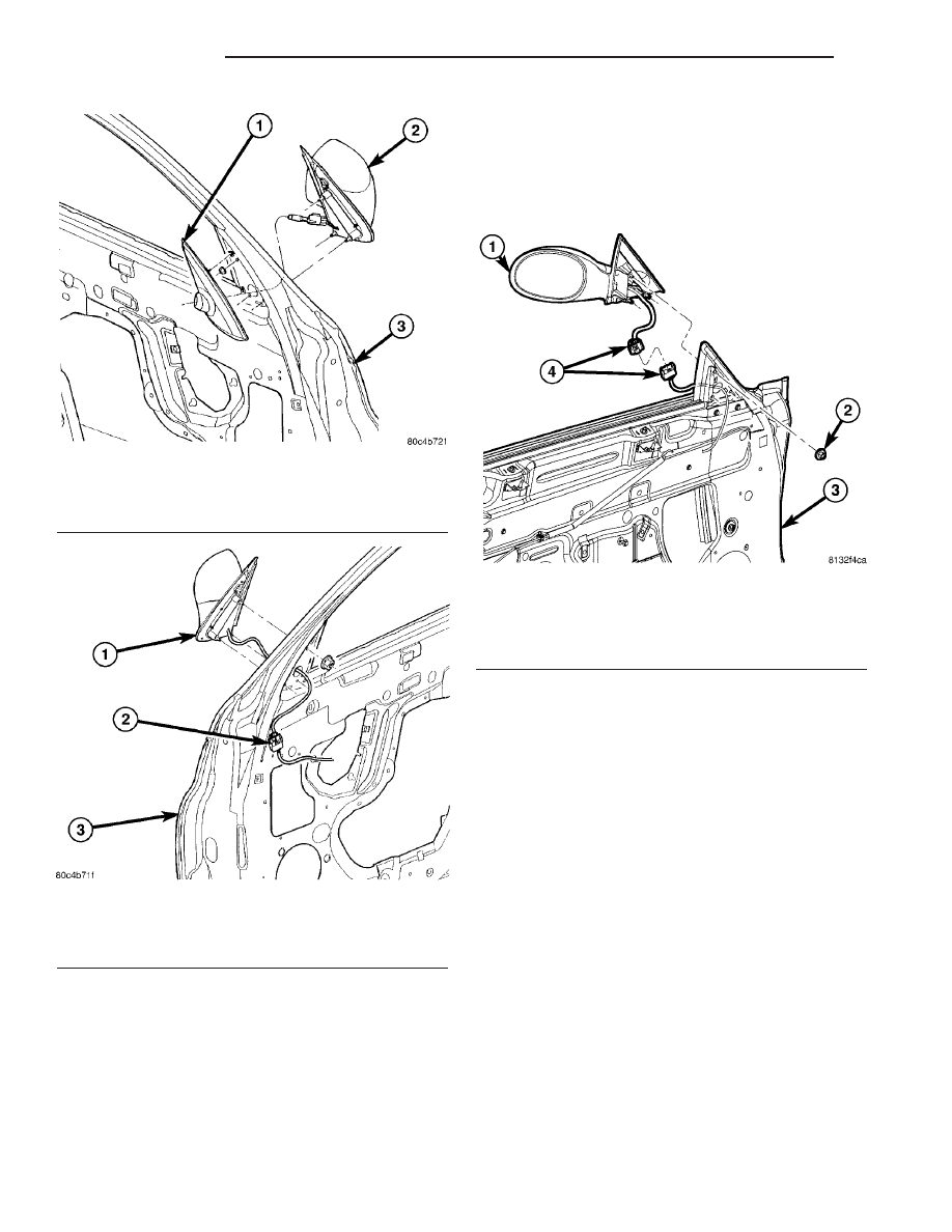
Fig. 16 MANUAL SIDE VIEW MIRROR

1 - INSIDE REMOTE CONTROL MIRROR BEZEL
2 - FRONT DOOR OUTSIDE REMOTE CONTROL MIRROR
3 - FRONT DOOR

Fig. 17 POWER SIDE VIEW MIRROR

1 - MIRROR
2 - WIRING CONNECTOR
3 - FRONT DOOR

Fig. 18 SIDE VIEW MIRROR ASSEMBLY

1 - MIRROR ASSEMBLY
2 - ATTACHING NUTS
3 - FRONT DOOR
4 - WIRE CONNECTORS

23 - 90

EXTERIOR

PT

SIDE VIEW MIRROR (Continued)

SIDE VIEW MIRROR GLASS

REMOVAL

WARNING: ALWAYS WEAR EYE AND HAND PRO-
TECTION WHEN SERVICING THE MIRROR ASSEM-
BLY. FAILURE TO OBSERVE THESE WARNINGS
MAY RESULT IN PERSONAL INJURY FROM BRO-
KEN GLASS.

(1) Push mirror glass to the fully inboard position

(Fig. 19).

(2) Carefully pull/pry mirror glass away from mir-

ror assembly until glass separates (Fig. 20).

(3) Disconnect the heated mirror electrical connec-

tors from the terminals on the mirror glass holder, if
equipped.

INSTALLATION

(1) Center the power pack pivot (Fig. 21).

(2) Place new mirror glass into position on mirror

assembly. Verify glass is centered on the power pack
base and in the correct position.

(3) Firmly press on the center of mirror glass until

a “pop” is heard and glass is fully seated (Fig. 22).

(4) Verify retention of the mirror glass by gently

pulling outward on the mirror glass.

Fig. 19 POSITION MIRROR

1 - PUSH MIRROR FULLY INBOARD

Fig. 20 REMOVE MIRROR GLASS

1 - FROM UNDERNEATH GLASS, PULL AWAY FROM MIRROR
ASSEMBLY

Fig. 21 CENTER POWER PIVOT

1 - CENTER PIVOT

Fig. 22 INSTALL MIRROR GLASS

1 - PRESS ON CENTER OF GLASS TO SEAT MIRROR GLASS

PT

EXTERIOR

23 - 91

WINDSHIELD A-PILLAR TRIM
MOLDING - PT-27

REMOVAL - PT-27 ONLY

(1) Remove header and A-piller weatherstrip as

necessary. (Refer to 23 - BODY/WEATHERSTRIP/
SEALS/HEADER/HEADER

AND

A-PILLAR

WEATHERSTRIP - REMOVAL).

(2) Remove screws attaching A-pillar weatherstrip

retainer and A-pillar molding to side of windshield
surround frame, the bottom screw which is hidden by
a piece of foam (Fig. 23), and remove the part by dis-
engaging the clips. (Refer to 23 - BODY/WEATHER-
STRIP/SEALS/A-PILLAR

WEATHERSTRIP

RETAINER - REMOVAL).

(3) Remove A-pillar molding from vehicle.

INSTALLATION - PT-27 ONLY

NOTE: A new A-pillar molding is used or replace the
clips that are damaged.

(1) Place A-pillar weatherstrip retainer and A-pil-

lar molding into position (Fig. 23).

(2) Engage clips attaching A-pillar weatherstrip

retainer and A-pillar molding to windshield surround
frame.

(3) Install screw attaching A-pillar weatherstrip

retainer and A-pillar molding (Refer to 23 - BODY/
WEATHERSTRIP/SEALS/A-PILLAR

WEATHER-

STRIP RETAINER - INSTALLATION).

(4) Install header and A-piller weatherstrip. (Refer

to 23 - BODY/WEATHERSTRIP/SEALS/HEADER/
HEADER

AND

A-PILLAR

WEATHERSTRIP

-

INSTALLATION).

(5) Raise top.

WOOD GRAIN/FLAME DECALS

REMOVAL

(1) Using a grease pencil or equivalent, mark the

location of the decals to aid installation.

(2) Using a heat gun, gently apply heat in a circu-

lar motion to loosen the adhesive bond.

(3) Using your fingernail, plastic or wood trim

stick, lift up and peel away the decal from the body
panel applying heat as you go (Fig. 24) or (Fig. 25).

(4) Clean off all traces of adhesive from the pan-

el(s) with a general purpose adhesive remover.

INSTALLATION

Surface Preparation

(1) Clean vehicle surfaces, removing any grease/oil

marks using a 50 percent mixture of a isopropyl alco-
hol and water or 3M

t High Performance Cloth.

(2) Dry surface using a lint free cloth.

Fig. 23 A-PILLAR MOLDING

1 - ATTACHING SCREW
2 - A-PILLAR MOLDING

23 - 92

EXTERIOR

PT

Application

NOTE: Decal and vehicle temperatures should be
between 13°C - 32°C (55°F - 90°F).

NOTE: Vehicle surface must be free of wax, grease,
oil, etc.

NOTE: Use detergent that is free of any lanolin or
lotions.

(1) Peel back liner from the decal by flicking a cor-

ner of the decal to separate the backing liner. Pull
the liner away at a 180° angle – taking care not to
let adhesive side of the decal touch clothing or fold
back on itself.

NOTE: For wood grain decals, do not allow the
back of the liner to get wet before peeling back film.
Pieces of wet liner paper will stick to the adhesive.

NOTE: Decals that have locating tabs: At times the
paper liner will remain on these tabs when remov-
ing the liner from the decals. This liner piece can be
left on the tabs, as it will not affect the locating abil-
ity of the tab and the tab will eventually be
removed.

(2) Using a detergent water solution made of 2-3

drops of detergent per liter (quart) of water, spray
decal application area and decal liberally.

(3) Apply the decal using the reference marks

made previously (Fig. 24) or (Fig. 25).

(4) Using a squeegee, start at the center of the

decal and squeegee out the wrinkles and liquid, fan-
ning out to the edges so as not to trap liquid and air.
Use one hand to squeegee and the other to keep the
decal from sliding on initial squeegee stroke. If the
decal has locating tabs, remove and discard the tabs
after the decal has been secured sufficiently.

(5) Wipe the surface with a cloth to remove the

any excess water. This may be helpful during the
squeegee process to visually inspect for bubbles and
wrinkles.

(6) Inspect the decal in good lighting conditions

from all angles for bubbles. Use the squeegee to push
bubbles to edges of the decal, forcing out air or water.
If bubbles do not move, the adhesive has already
been wetted out. A pin or equivalent tool may be
used as an air release tool to pop the bubble and
release the air and or wetting solution. Gently use a
squeegee over the area to release the water after
using the air release tool.

Fig. 24 WOOD GRAIN OVERLAYS AND MOLDINGS

1 - LIFTGATE OVERLAY
2 - REAR DOOR OVERLAY
3 - FRONT DOOR OVERLAY
4 - FRONT FENDER MOLDING
5 - FRONT DOOR MOLDING

6 - REAR DOOR MOLDING
7 - FUEL FILLER DOOR MOLDING
8 - QUARTER PANEL OVERLAY
9 - QUARTER PANEL MOLDING
10 - LIFTGATE MOLDING

PT

EXTERIOR

23 - 93

WOOD GRAIN/FLAME DECALS (Continued)


Content   ..  906  907  908  909   ..