Chrysler PT Cruiser. Manual - part 853
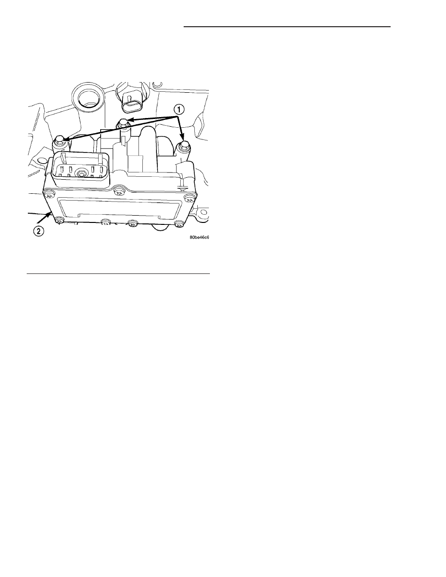
(69) Install and tighten solenoid/pressure switch
assembly-to-transaxle case bolts to 12 N·m (110 in.
lbs.) (Fig. 163).
(70) Install and torque input and output speed
sensors to case to 27 N·m (20 ft. lbs.).
INSTALLATION
(1) Install transaxle to engine (Fig. 19). Install and
torque transaxle-to-engine bolts to 108 N·m (80 ft.
lbs.).
(2) Raise engine/transaxle assembly enough line
up transaxle mount bracket. Install two mount-to-
transaxle bracket bolts (Fig. 18)and torque to 68 N·m
(50 ft. lbs.).
(3) Remove screw jack support.
(4) Install
four
drive
plate-to-torque
converter
bolts and torque to 88 N·m (65 ft. lbs.) torque.
(5) Position starter into place and hand-tighten
lower bolt.
(6) Lower vehicle.
(7) Install transaxle dipstick tube. Verify that
openings are free of debris and o-ring seal is intact.
Replace o-ring if necessary. Secure bracket to trans-
axle. Install starter upper bolt through the ground
cable and torque to (40 ft. lbs.).
(8) Install cable bracket-to-transaxle bellhousing
bolt and torque to 61 N·m (45 ft. lbs.).
(9) Raise vehicle.
(10) Torque starter lower bolt (Fig. 17) to 54 N·m
(40 ft. lbs.).
(11) Connect starter motor electrical connections.
(12) Install bellhousing dust cover (Fig. 15).
(13) Install structural collar and left (front) lateral
bending brace. Refer to ENGINE for proper proce-
dures (Fig. 14).
(14) Install right (rear) lateral bending brace (Fig.
16). Torque bolts to 81 N·m (60 ft. lbs.) torque.
(15) Install power steering line to structural collar
(Fig. 13).
(16) Install front halfshafts. Refer to DIFFEREN-
TIAL AND DRIVELINE for proper procedures and
torque specifications.
(17) Install left splash shield.
(18) Install left wheel/tire assembly. Torque lug
nuts to 136 N·m (100 ft. lbs.) torque.
(19) Lower vehicle.
(20) Connect transaxle oil cooler lines. An audible
’click’ should be heard. Verify connection by pulling
outward. (Refer to 7 - COOLING/TRANSMISSION -
STANDARD PROCEDURE)
(21) Connect solenoid/pressure switch assembly
connector (Fig. 12).
(22) Connect transmission range sensor connector
(Fig. 12).
(23) Connect output speed sensor connector (Fig.
12).
(24) Connect input speed sensor connector (Fig.
12).
(25) Install gearshift cable to bracket and connect
to the manual valve lever.
(26) Install battery tray (Fig. 11).
(27) Install battery and hold-down clamp (Fig. 10).
(28) Install air cleaner assembly (Fig. 9).
(29) Connect battery cables.
(30) Fill transaxle with fluid. Refer to SERVICE
PROCEDURES for proper procedure.
Fig. 163 Solenoid Pack-to-Transaxle Bolts
1 - BOLTS
2 - SOLENOID AND PRESSURE SWITCH ASSEMBLY
21 - 366
41TE AUTOMATIC TRANSAXLE
PT
41TE AUTOMATIC TRANSAXLE (Continued)