Chrysler PT Cruiser. Manual - part 829


  Index      Chrysler     Chrysler PT Cruiser - service repair manual 2005 year


Search            


Content   ..  827  828  829  830   ..


Chrysler PT Cruiser. Manual - part 829


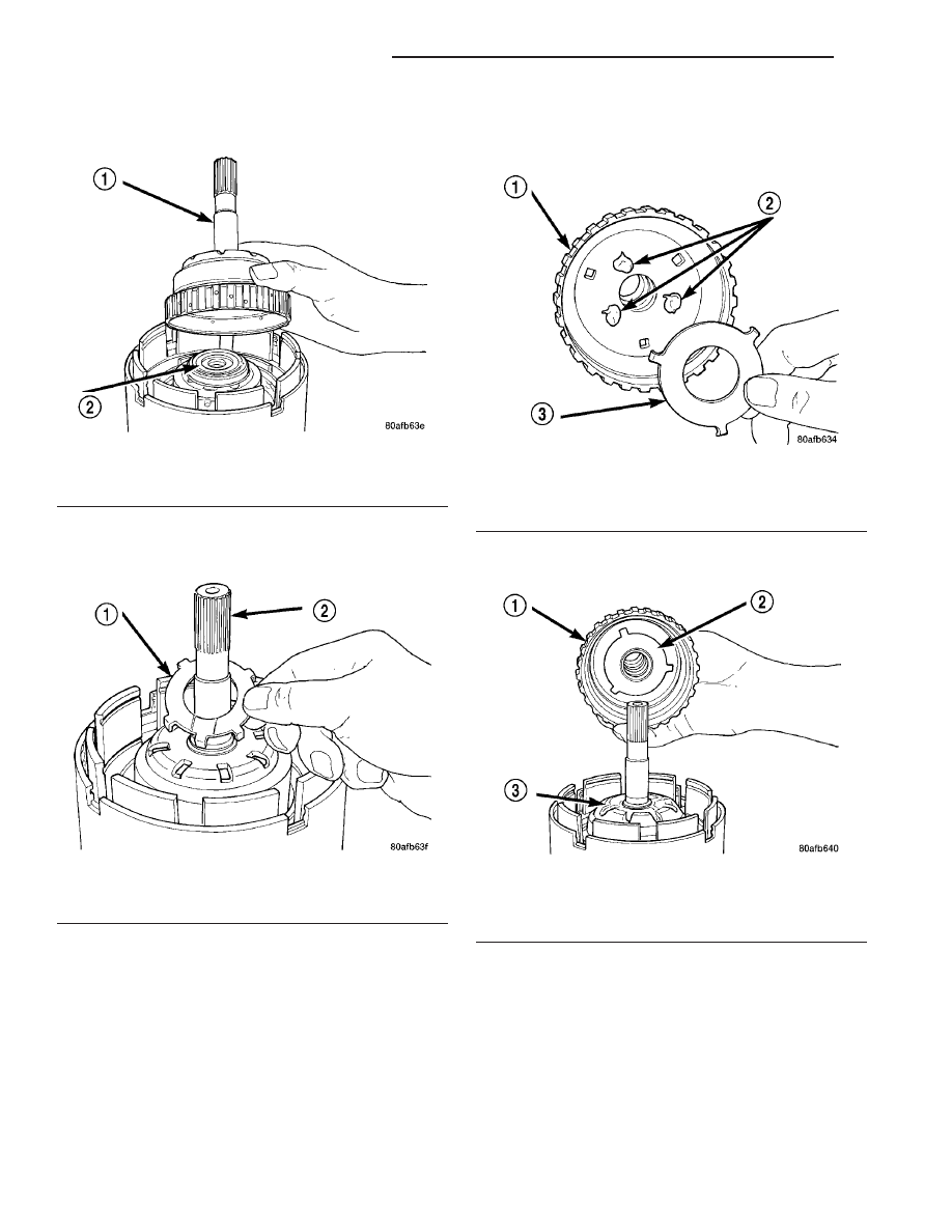
(38) Install the underdrive shaft assembly (Fig.

287).

(39) Install the #3 thrust washer to the underdrive

shaft assembly. Be sure five tabs are seated properly
(Fig. 288).

(40) Install the #3 thrust plate to the bottom of the

overdrive shaft assembly. Retain with petrolatum or
transmission assembly gel (Fig. 289).

(41) Install the overdrive shaft assembly (Fig. 290)

(Fig. 291).

Fig. 287 Install Underdrive Shaft Assembly

1 - UNDERDRIVE SHAFT ASSEMBLY
2 - #2 NEEDLE BEARING

Fig. 288 Install No. 3 Thrust Washer

1 - #3 THRUST WASHER (NOTE 5 TABS)
2 - UNDERDRIVE SHAFT ASSEMBLY

Fig. 289 Install No. 3 Thrust Plate

1 - OVERDRIVE SHAFT ASSEMBLY
2 - DABS OF PETROLATUM (FOR RETENTION)
3 - #3 THRUST PLATE (NOTE 3 TABS)

Fig. 290 Install Overdrive Shaft Assembly

1 - OVERDRIVE SHAFT ASSEMBLY
2 - #3 THRUST PLATE
3 - #3 THRUST WASHER

21 - 270

40TE AUTOMATIC TRANSAXLE

PT

INPUT CLUTCH ASSEMBLY (Continued)

(42) Reinstall overdrive and reverse clutch as

shown. Rechecking these clutch clearances is
not necessary.

Fig. 291 Overdrive/Underdrive Shafts

1 - OVERDRIVE SHAFT
2 - #3 THRUST PLATE (3 TABS)
3 - #3 THRUST WASHER (5 TABS)

4 - UNDERDRIVE SHAFT
5 - #2 NEEDLE BEARING (3 TABS)
6 - INPUT CLUTCH ASSEMBLY

PT

40TE AUTOMATIC TRANSAXLE

21 - 271

INPUT CLUTCH ASSEMBLY (Continued)

OIL PUMP

DESCRIPTION

The oil pump is located in the pump housing inside

the bell housing of the transaxle case (Fig. 292). The
oil pump consists of an inner and outer gear, a hous-
ing, and a cover that also serves as the reaction shaft
support.

OPERATION

As the torque converter rotates, the converter hub

rotates the inner and outer gears. As the gears
rotate,

the

clearance

between

the

gear

teeth

increases in the crescent area, and creates a suction
at the inlet side of the pump. This suction draws
fluid through the pump inlet from the oil pan. As the
clearance between the gear teeth in the crescent area
decreases, it forces pressurized fluid into the pump
outlet and to the valve body.

DISASSEMBLY

When disassembling the transaxle it is necessary

to inspect the oil pump for wear and damage.

(1) Remove the reaction shaft support-to-pump

body bolts (Fig. 293).

(2) Remove reaction shaft support from pump

housing (Fig. 294).

Fig. 292 Oil Pump Assembly

1 - PUMP BODY
2 - OUTER GEAR
3 - INNER GEAR
4 - REACTION SHAFT SUPPORT
5 - SEAL RINGS (4)
6 - REACTION SHAFT
7 - CRESCENT

Fig. 293 Reaction Support-to-Pump Body Bolts

1 - BOLT (6)
2 - PUMP BODY
3 - REACTION SHAFT SUPPORT

Fig. 294 Reaction Shaft Support

1 - PUMP BODY
2 - PUMP GEARS
3 - REACTION SHAFT SUPPORT

21 - 272

40TE AUTOMATIC TRANSAXLE

PT

(3) Remove the pump gears (Fig. 295) and check

for wear and damage on pump housing and gears.

(4) Re-install the gears and check clearances.
(5) Measure the clearance between the outer gear

and the pump pocket (Fig. 296). Clearance should be
0.089–0.202 mm (0.0035-0.0079 in.).

(6) Measure clearance between outer gear and

crescent (Fig. 297). Clearance should be 0.060-0.298
mm (0.0023-0.0117 in.).

(7) Measure clearance between inner gear and

crescent (Fig. 298). Clearance should be 0.093-0.385
mm (0.0036-0.0151 in.).

Fig. 295 Oil Pump Assembly

1 - PUMP BODY
2 - OUTER GEAR
3 - INNER GEAR
4 - REACTION SHAFT SUPPORT
5 - SEAL RINGS (4)
6 - REACTION SHAFT
7 - CRESCENT

Fig. 296 Measuring Outer Gear-to-Pocket

1 - FEELER GAUGE
2 - OUTER GEAR
3 - PUMP BODY

Fig. 297 Measuring Outer Gear-to-Crescent

1 - FEELER GAUGE
2 - OUTER GEAR
3 - CRESCENT
4 - INNER GEAR

Fig. 298 Measuring Inner Gear-to-Crescent

1 - FEELER GAUGE
2 - OUTER GEAR
3 - CRESCENT
4 - INNER GEAR

PT

40TE AUTOMATIC TRANSAXLE

21 - 273

OIL PUMP (Continued)


Content   ..  827  828  829  830   ..